1.5.1 Table of Vehicle Handbook Information on
Child
Restraint Systems
installation suitability for various seating positions

- Do not use blower or infotainment system in idle condition.
- Ensure all doors, hood and tail gate are properly locked.
- Shift to P before switching off ignition.
- Please do not use Accelerator & Brake pedal simultaneously.
- Prohibited to drive the vehicle in flood / high water level conditions.
FOREWORD
Thank you for selecting JSW MG Vehicle!
Your vehicle is integrated with advanced technologies, safety, environmental protection and economy.
This manual provides necessary information to help you drive your vehicle safely and effectively. The driver shall always note that improper operation of vehicle may cause the risk of accidents and injuries. To ensure optimal usage and maintenance of your MG, please thoroughly review this manual and save it securely once you have finished.
Special Instructions: We advise using genuine spare parts and following this manual for proper vehicle use, maintenance, and repairs. Substituting or altering the vehicle with non-genuine spare parts can compromise overall performance, particularly safety and durability. Any vehicle damage or performance issues resulting from non-genuine spare parts are not covered under warranty. Furthermore, vehicle modifications may infringe government regulations.
To enhance our service to you, please verify that your contact information is up to date. If there are any changes, please contact an authorized JSW MG dealer to ensure our records are accurate. It is crucial to comply with national laws and local regulations and to promptly register your vehicle to prevent any potential registration issues.
The descriptions marked with "*" in this manual apply specifically to certain models, and the images depict a single configuration. In case of any differences with your vehicle, the actual configuration takes precedence.
Pay close attention to the "NOTE", "CAUTION", "DANGER" and "WARNING" symbols in this manual, and carefully follow the instructions to prevent injury or damage. The definitions of these symbols are as follows:

Items that must be observed to
facilitate maintenance, etc.

Indicates an operation that should
be avoided or should not occur.

Items that must be observed to
avoid damage to the vehicle.

Indicates risks of accidents or
injuries. Ignoring such information
may lead to injuries or property loss.
This manual aims to assist you in appropriately using the product and does not include details about its configuration and software version. For information on those aspects, please refer to the product’s brochure or consult the dealer from whom you purchased the vehicle.
MG operates a policy of constant product improvement and therefore reserves the right to change specifications without notice at any time. Whilst every effort is made to ensure complete accuracy of the information in this publication, no liabilities for inaccuracies or damage to property, or injury to persons, can be accepted by the manufacturer or JSW MG authorised service center who supplied the publication, except in respect of personal injury caused by the negligence of the manufacturer or JSW MG authorised service center.
In case you require assistance or clarifications please visit nearest dealer or contact us at 24 hours Helpline at 1800 100 6464 or email us at: pulsehub@ mgmotor.co.in
Copyright © JSW MG Motor India Ltd. All rights reserved. No part of this document may be reproduced or transmitted in any form or by any means without prior written consent of JSW MG Motor India .


Before You Drive
1.1 Headrest
Position
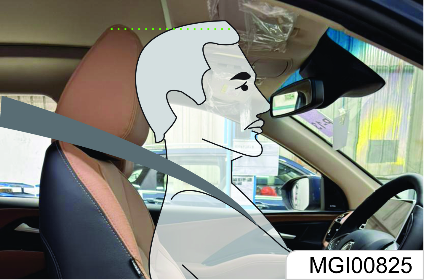
The middle position of the headrest should be on the same horizontal line as the occupant’s eyes. For tall persons, if the above point cannot be met, the headrest shall be adjusted to the highest position; for short persons, the headrest shall be adjusted to the lowest position.
Before driving, make sure that the headrest is adjusted properly.
Removal or improper adjustment of the headrest will cause severe injuries to the head and neck in collision accidents.
Height Adjustment
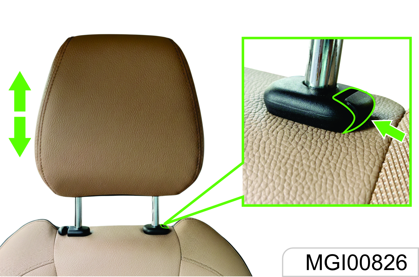
To adjust the headrest upward, pull the headrest upward to a proper position and fix it. To remove the headrest, press and hold the release switch.
To adjust the headrest downward, press and hold the release switch and push the headrest downward to a proper position; then, release the release switch for fixation.
Pay attention not to press the headrest forcibly to avoid injuring the finger while pressing the release switch.
1.2 Front Seat
Seat Position and Backrest Normal Condition
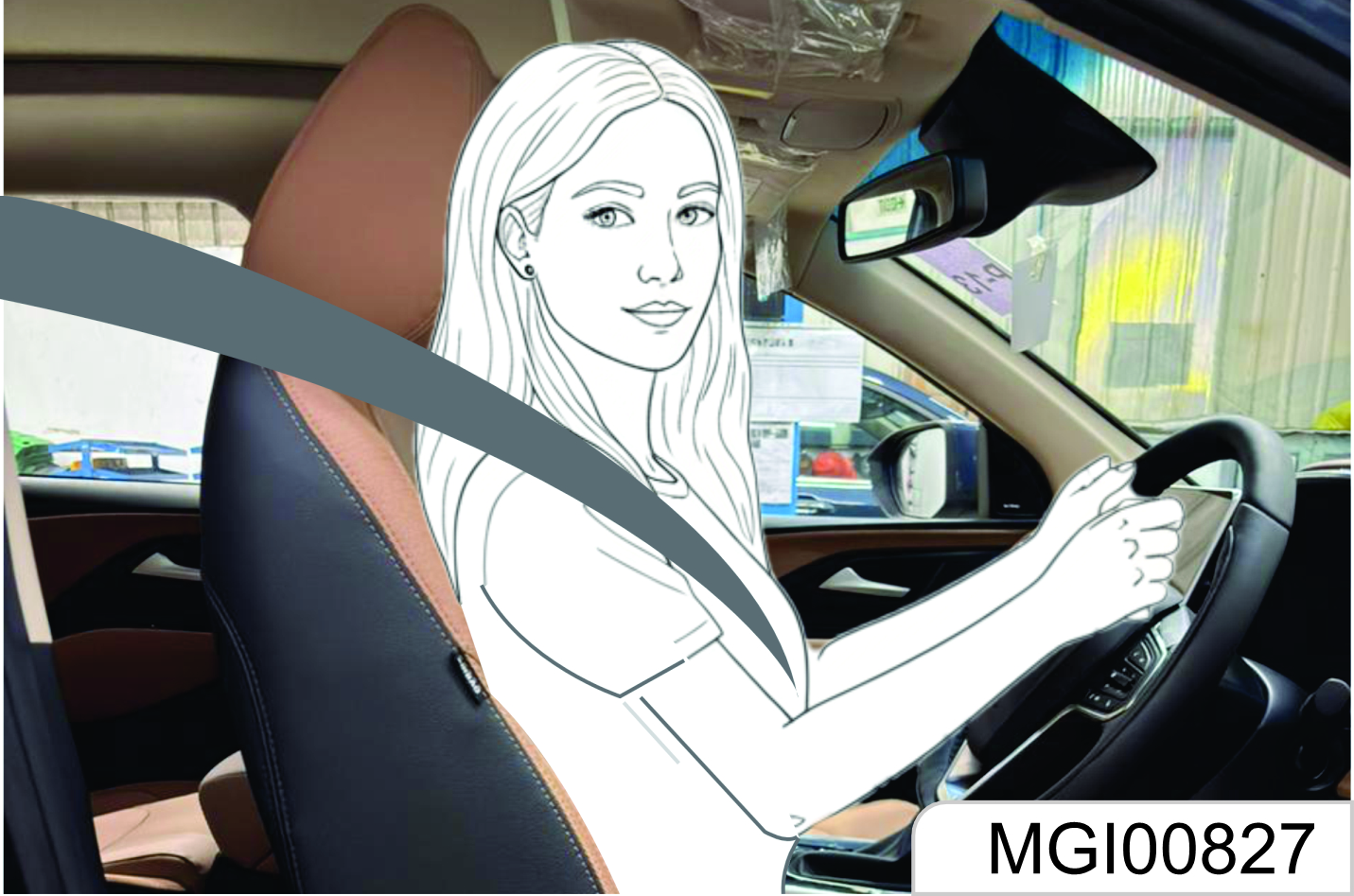
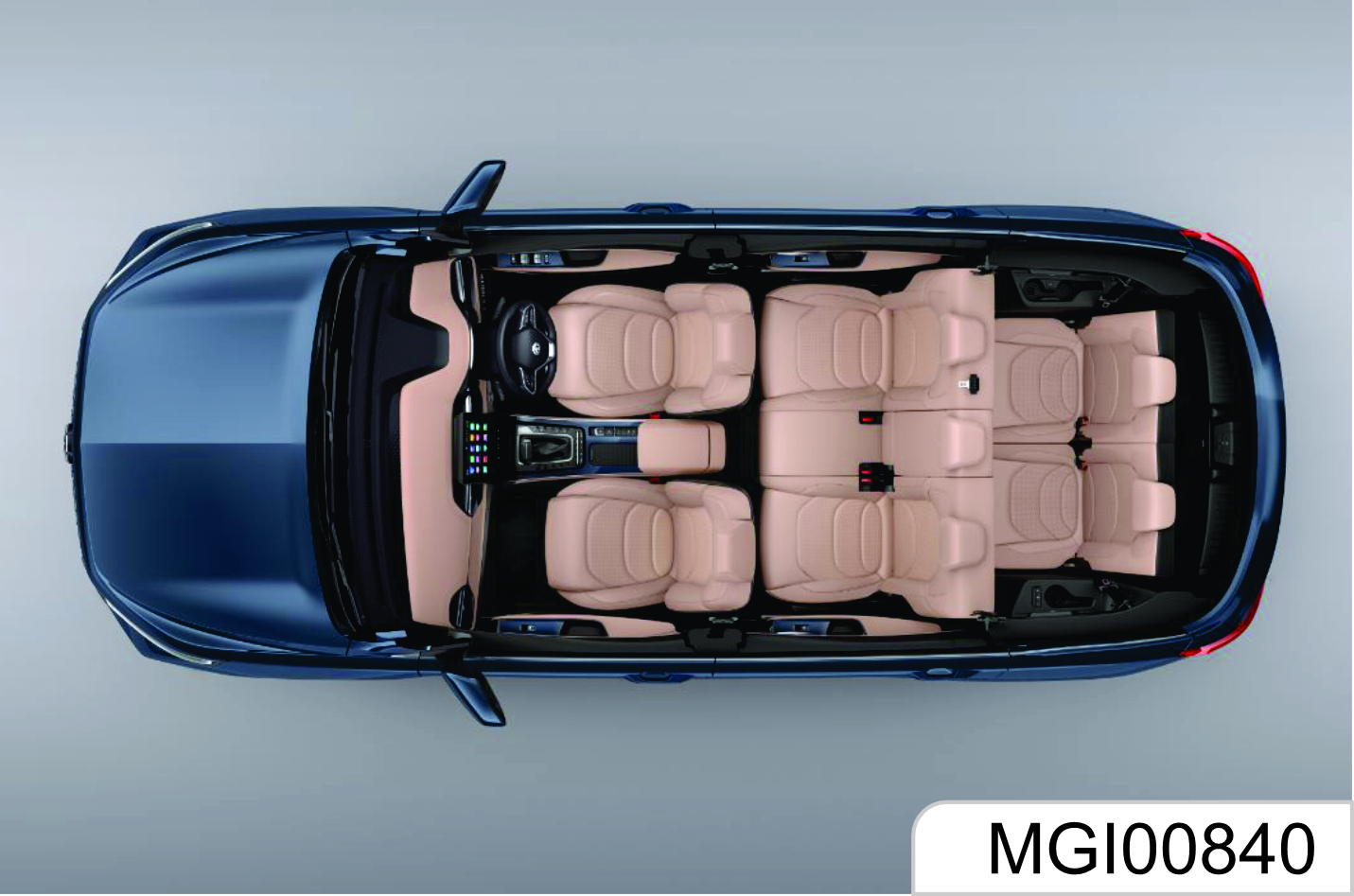
- When you sit on the seat, make your hips as close as possible to the backrest. Adjust the distance between the seat and the pedal to make your leg slightly bend when you press the pedal. The passenger’s seat shall slide as backward as possible.
- When you sit on the seat, make your shoulders lean on the backrest as backward as possible. Set the backrest inclination angle to make your arm conveniently to reach the steering wheel while slightly bending the arm. Keep the shoulders leaning against the backrest while turning the steering wheel. The backrest shall not incline excessively backward.
- The seat height shall be so set that the occupant can see all directions and the positions of all display instruments. The head must be at least one hand away from the roof lining The thighs are right on the seat without constriction.
Before driving, make sure that the headrest is adjusted properly. Removal or improper adjustment of the headrest will cause severe injuries to the head and neck in collision accidents.
1.2.1 Seat Position Adjustment
Manual Adjustment Type*
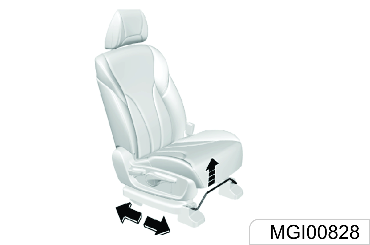
Pull the adjustment lever on the front lower part of the seat upward to adjust the seat forward or backward, and release the lever after the seat is adjusted to a proper position.
Try to slide the seat forward and backward to ensure that the seat is locked at a proper position.
Electric Adjustment Type*
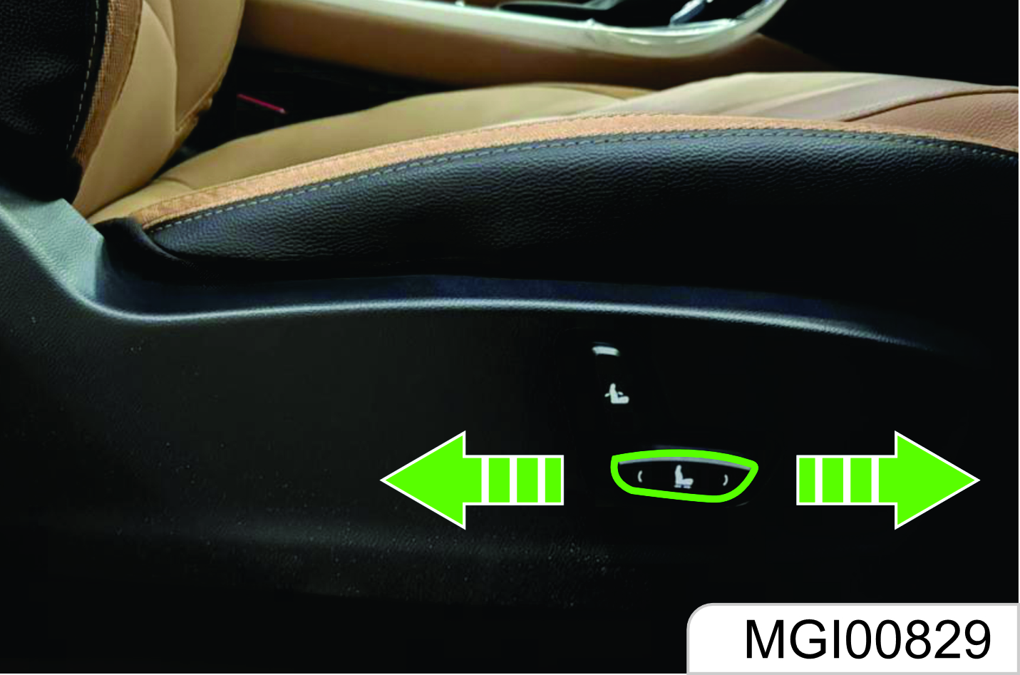
As shown in the figure, the electric adjustment switch is on the outer side of the seat. Push the switch forward or backward, and the seat will move forward or backward accordingly. Release the switch when it reaches a proper position.
If the seat does not move when the switch is pushed, the seat may be already at the front or rear maximum limit position, or the vehicle battery is out of power. Please check for confirmation. Never turn the switch forcibly to avoid damaging it.
1.2.2 Seat Backrest Adjustment
Manual Adjustment Type*
As shown in the figure, the electric adjustment switch is on the outer side of the seat. Push the switch forward or backward, and the seat will move forward or backward respectively. Release the switch when it reaches a proper position.
Electric Adjustment Type*
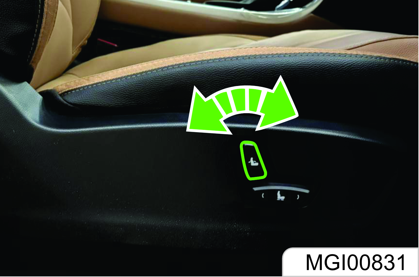
As shown in the figure, turn the adjustment switch forward and backward, and the backrest will be folded forward or unfolded backward respectively. Release the switch when it is adjusted to a proper position.
If the backrest does not move when the switch is turned, the backrest may be already at maximum limit position, or the vehicle battery is out of power. Please check for confirmation. Never turn the switch forcibly to avoid damaging it.
The backrest plays an important protection role when the vehicle is running. Unlocked backrest may cause severe personal injuries in case of sudden braking or a collision. Any time after adjusting the seat backrest, shake the backrest to check whether it is locked even though no passenger occupies the seat.
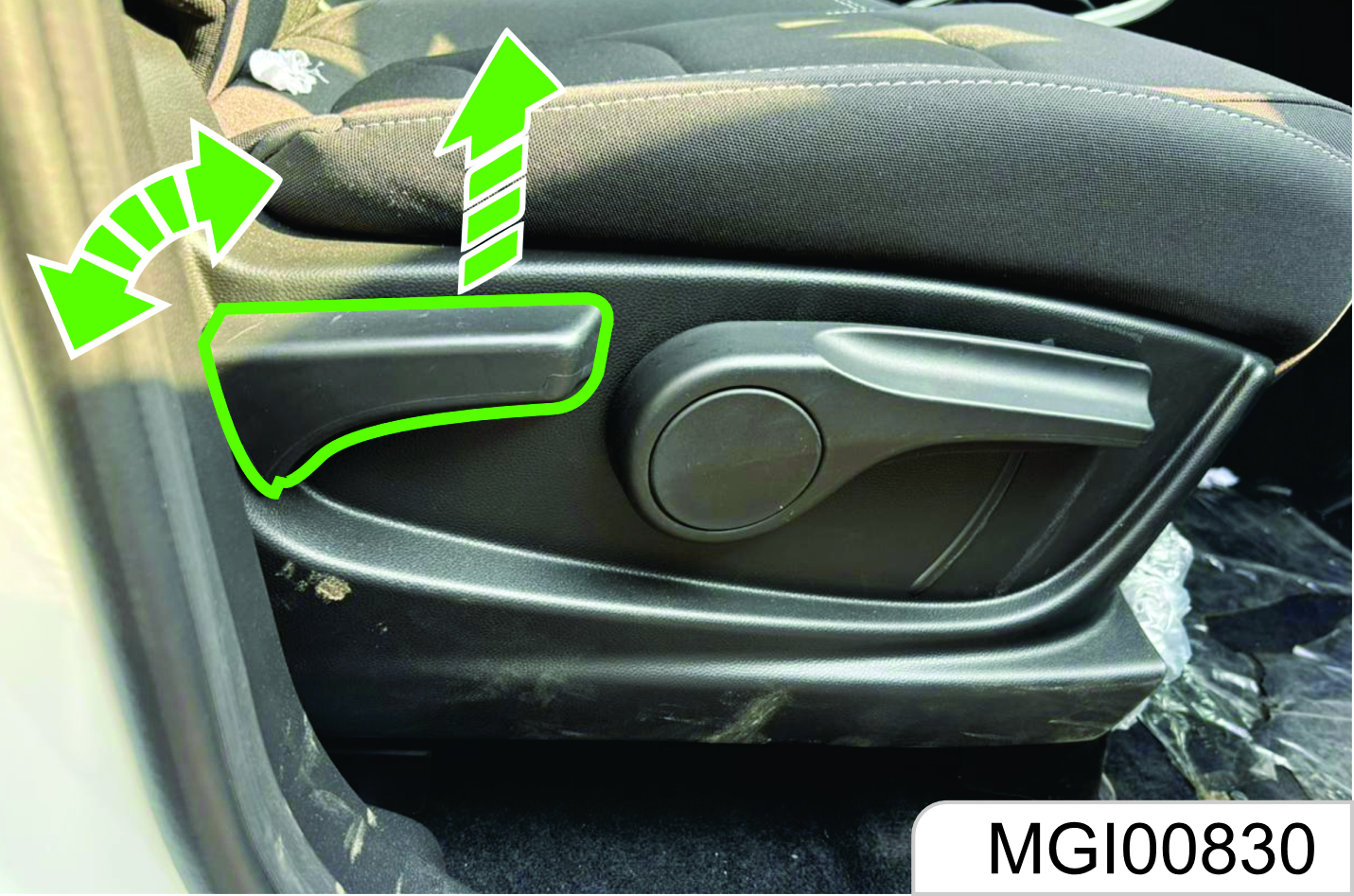
1.2.3 Driver’s Seat Height Adjustment
Manual Adjustment Type*
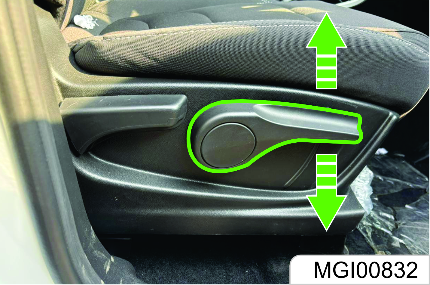
Turn the handle on the outer side of the seat upward and downward until the seat is adjusted to the desired height. While adjusting the seat height, the seat must be loaded. Therefore, please sit on the seat before adjustment; otherwise, the adjustment device may be damaged.
Electric Adjustment Type*
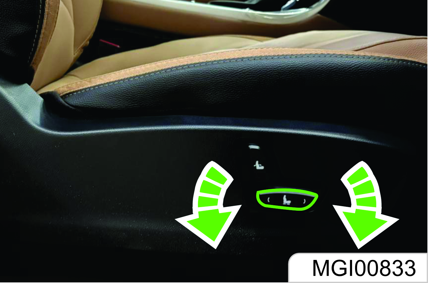
As shown in the figure, rotate the height adjustment switch on the outer side of the seat cushion, and then release the switch after the seat is adjusted to proper height.
The electrically adjustable front passenger’s seat cannot be adjusted upward or downward.
1.3 Rear Seat Backrest Adjustment and Folding
1.3.1 Rear Seat (5-Seat Model)
Rear seat cannot be adjusted forward or backward.
Armrest
As shown in the figure, the second row seat is configured with an armrest. Deploy the armrest for use. There is a cup holder on the armrest. After use, please put back the armrest.
Seat Position and Backrest Angle for Measurement of Seat Cushion Thickness.
For measurement of the seat cushion thickness, the seat can be in any position.
The seat backrest shall incline backward for a certain angle from the vertical position. The angle is 23°, 25° and 20° respectively for the 1st and 2nd row.
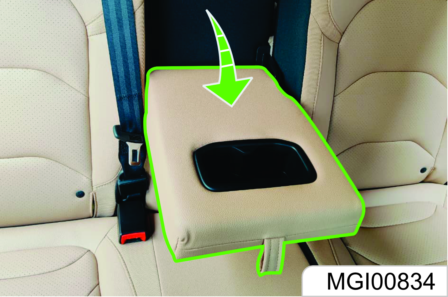
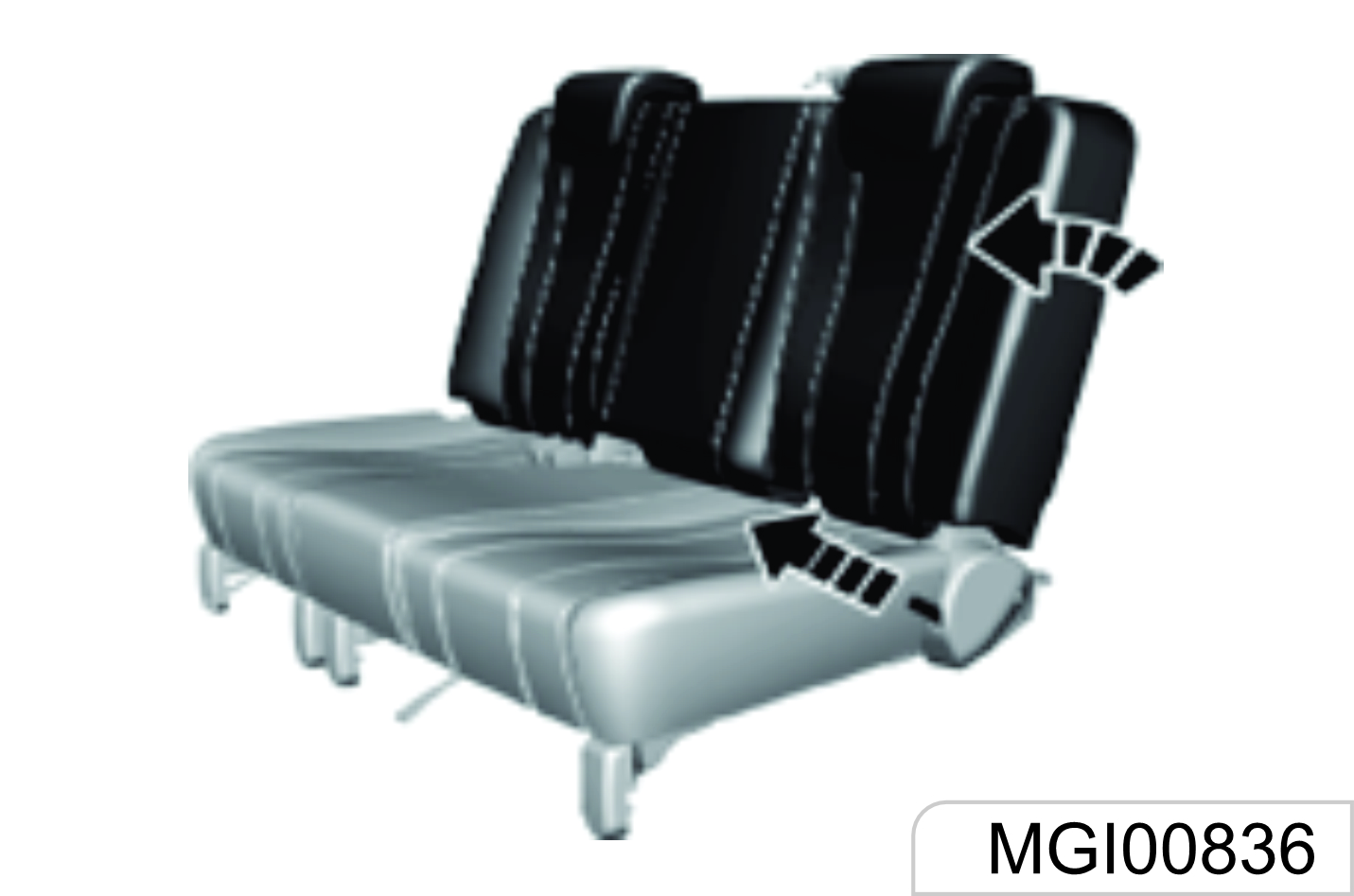
Middle Row Seat
As shown in the figure, after the cushion is unlocked, pull out the cushion forward and lift up the rear part of the cushion to overturn it. The two cushions can all be overturned.
To recover, install the cushion back in opposite order, and press down the cushion with force. Try to shake the seat cushion to make sure that it is locked.
1.3.2 7 Seat Variant
The seat backrest inclination angle is adjustable within a certain range.
First hold the backrest with your hands because the backrest will be folded quickly and may cause impact or injuries after the backrest release belt is pulled up. Then, pull the backrest release strap on the seat side backward, and release the strap after a proper angle is obtained.
To fold the seat backrest, pull up the strap and fold the backrest forward. Overturning the seat cushion first and then folding the backrest can fold flat the backrest to the greatest extent.
To recover, pull up the strap and unfold the backrest to a proper angle. Finally, try to shake the backrest to check whether it is fixed.
Hold the backrest first and do not make the head or other body parts within the backrest folding range before pulling the backrest drawstring and folding the backrest. 0therwise, the backrest will be folded quickly and may cause impact or injuries.
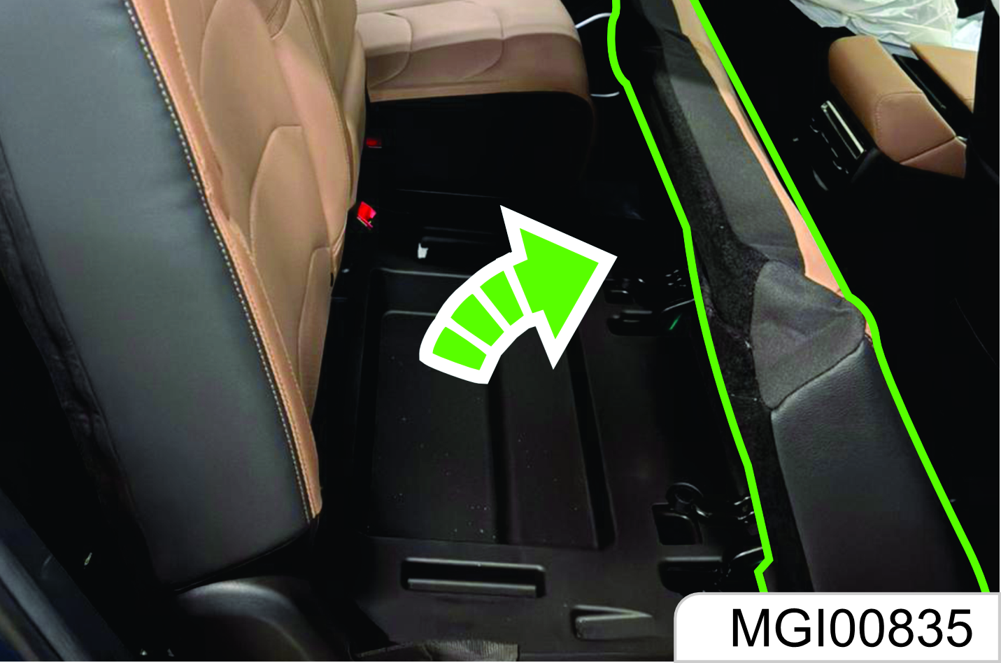
Seat Overturn
For the 7-seater variant, when you need to sit at the rear seat you can overturn the left side of middle row seat. As shown in the figure, you can pull the lever until the seat lock is detached. To recover, pull up the lever and push back the seat until it safely locked in position.
Seat Backrest Folding
As shown in the figure, pull the strap on the back of the seat and fold the backrest forward. To recover, pull the drawstring and unfold the backrest until it is locked in position.
1.3.3 Seat Layout Diagram
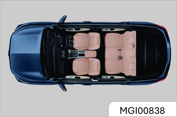
5-Seater Layout Diagram
6-Seater Layout Diagram
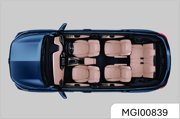
7-Seater Layout Diagram
1.4 Seat Belt
The seat belt is designed only for one passenger each time. It is not applicable to a passenger under 12 years old or under 150 cm high. Check all parts of the seat belt system for damage and abnormal function regularly. Please replace the damaged parts and components. It is strongly recommended to have the seat belt or deployed seat belt tensioner replaced at the JSW MG Authorized Service Center after an accident.
Seat Belt Force Limiter*
It is configured on the seat belts for the driver’s seat and the left seat of second row. For some models, the front passenger’s seat belt is also configured with a force limiter.
The force limiter can reduce the stress applied on the body through the seat belt damping release in case of a collision accident.
Seat Belt Pretensioner*
Depending on different models, it is configured on the seat belt for the driver’s seat, front passenger’s seat
of the left seat of the second row. In case of a severe head-on or rear-end collision, the front part of the seat belt will be tensioned.
The deployed seat belt pretensioner must be replaced by the JSW MG Authorized Service Center. The seat belt pretensioner can only be deployed once.
Make sure that the seat belt is not damaged or clamped by a sharp object. Prevent dust from getting in the seat belt recoiler.
Improper operation (for example removal or installation of seat belt or seat belt anchor buckle) will trigger the seat belt tensioner, leading to injury risks.
Buckle the seat belt each time before driving the vehicle. In case of an accident, a passenger who does not buckle the seat belt may be at risk.
It is not allowed to add any accessory or other object that may interference with the operation of the seat belt. Do not change any seat belt component.
The seat belt shall not be buckled against a hard or fragile object in your pocket. otherwise, the hard object will hurt you and the fragile object may be damaged in case of emergencies.
Pay attention to prevent foreign matters from getting in the seat belt buckle (such as sunflower seed shell and button); otherwise, the seat belt buckle will fail.
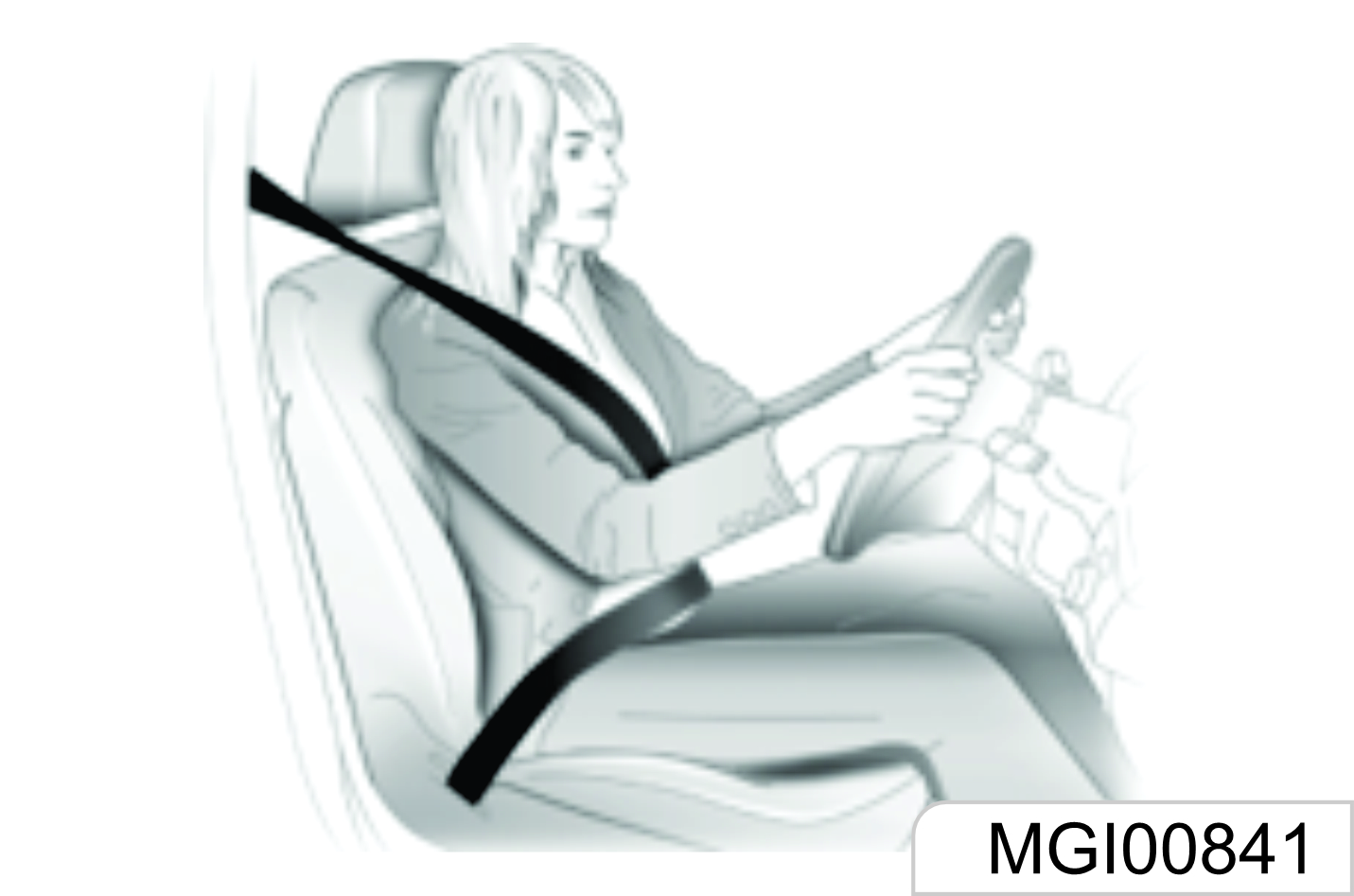
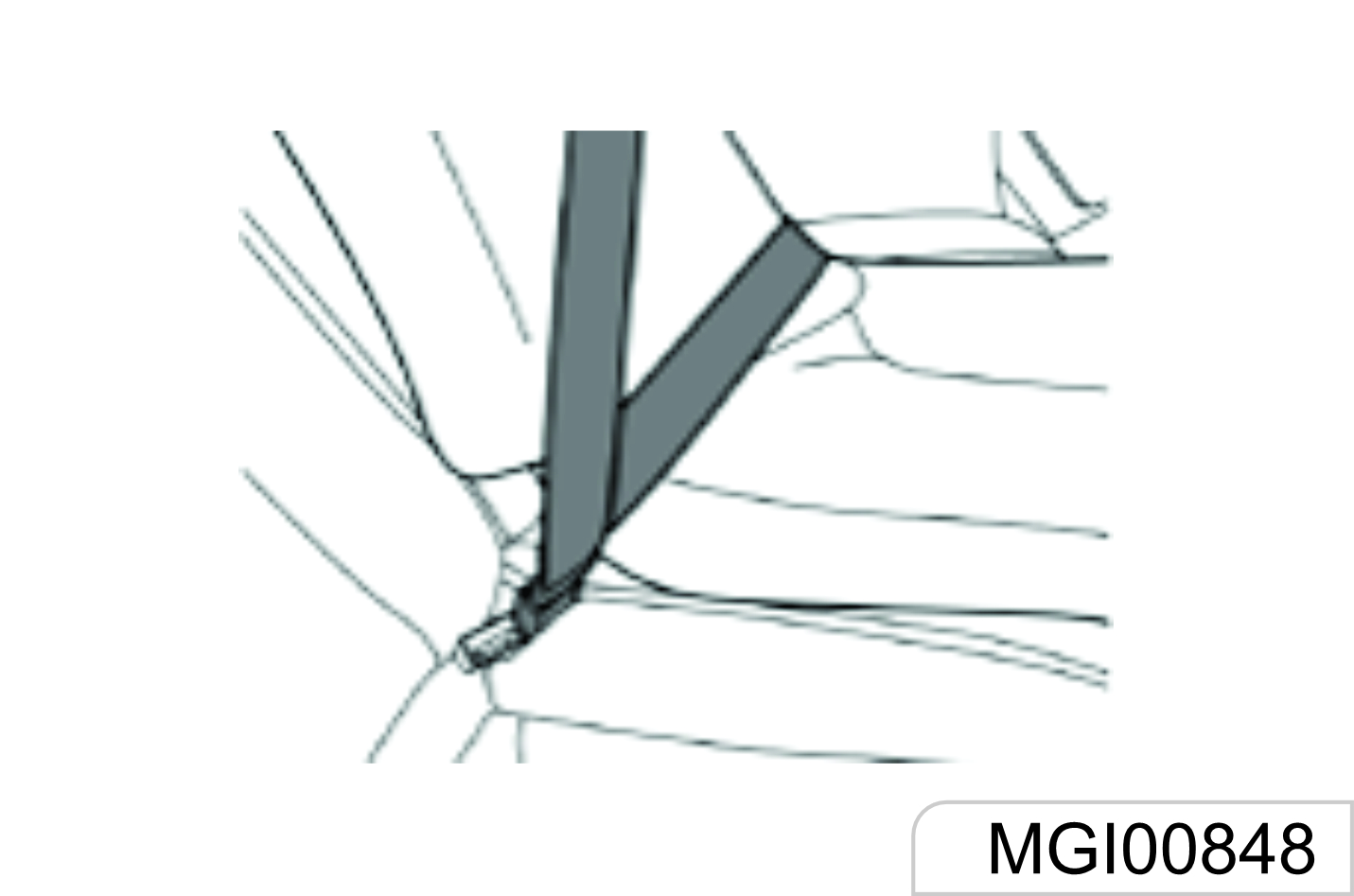
Wearing
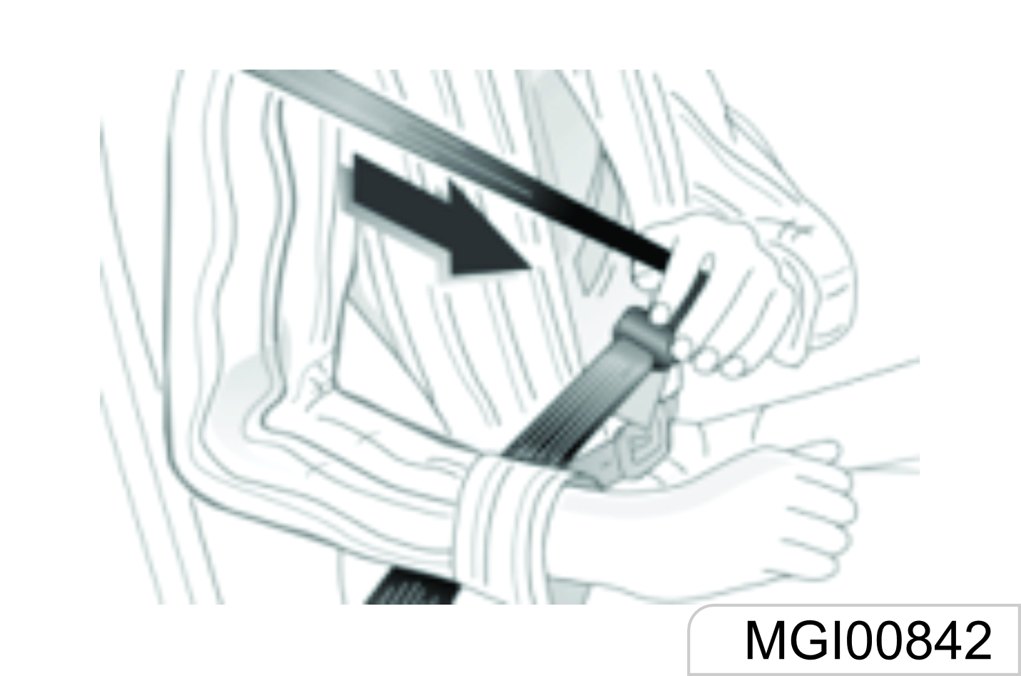
- Pull out the seat belt from the recoiler, and fasten it across the body without twisting
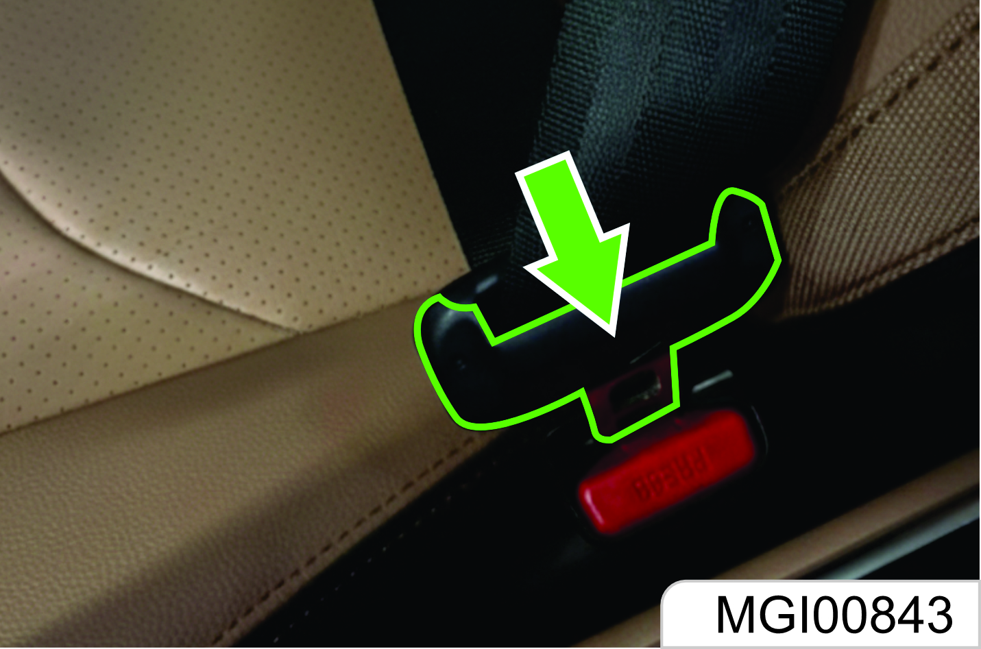
- Put the latch plate in the buckle for fixing. Pull the shoulder belt forcibly to adjust the tightness degree of hip belt.
Loose or heavy clothing will hamper close wearing the seat belt. Do not place any object (such as handbag and mobile phone) between the seat belt and your body.
Height Adjustment*
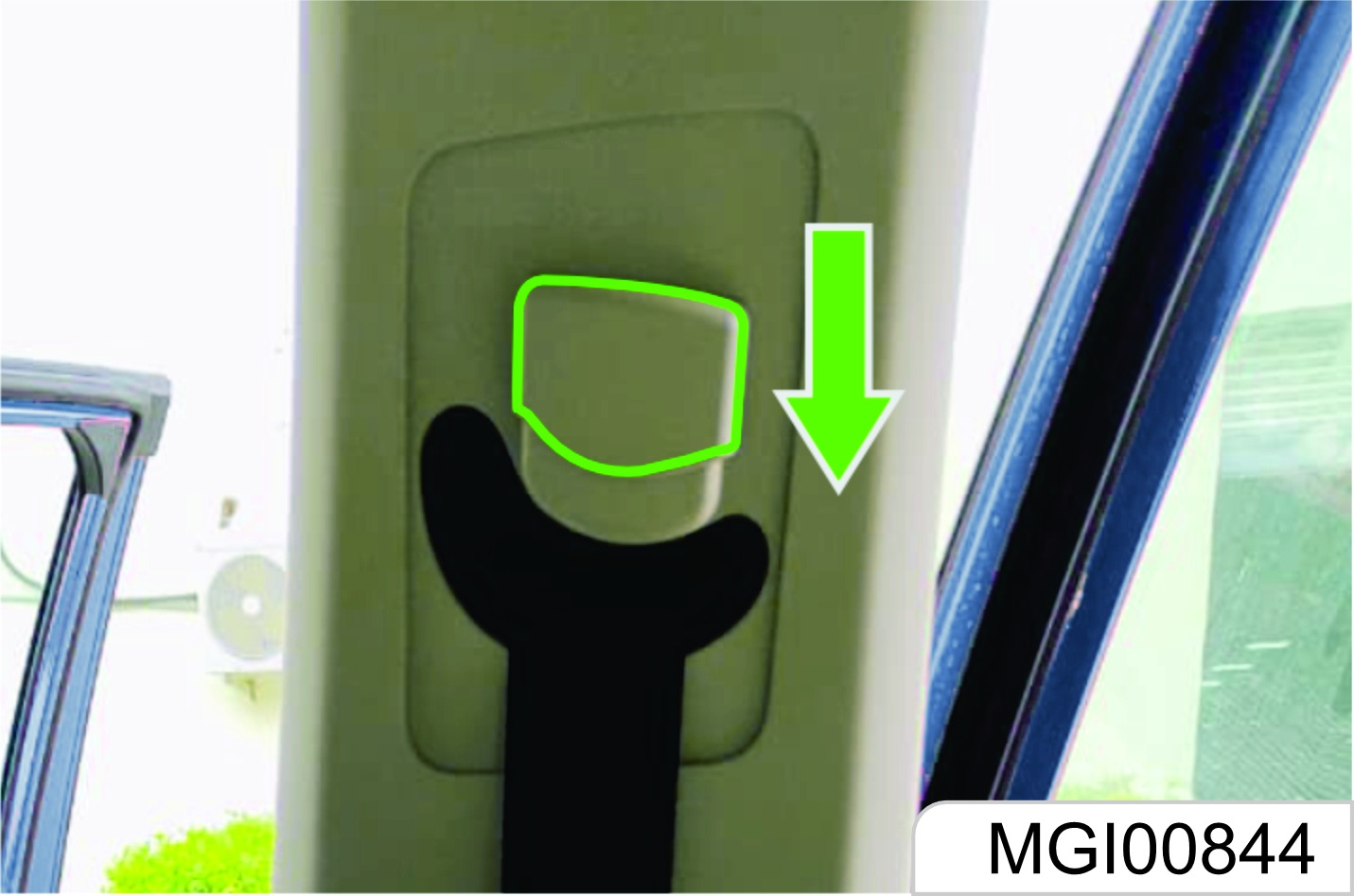
Depending on different models, the front row seat belt of some models can be adjusted in height. Press the height adjuster of the seat belt upper fixing point and move it upward or downward. Release the adjuster after adjustment.
Unbuckle
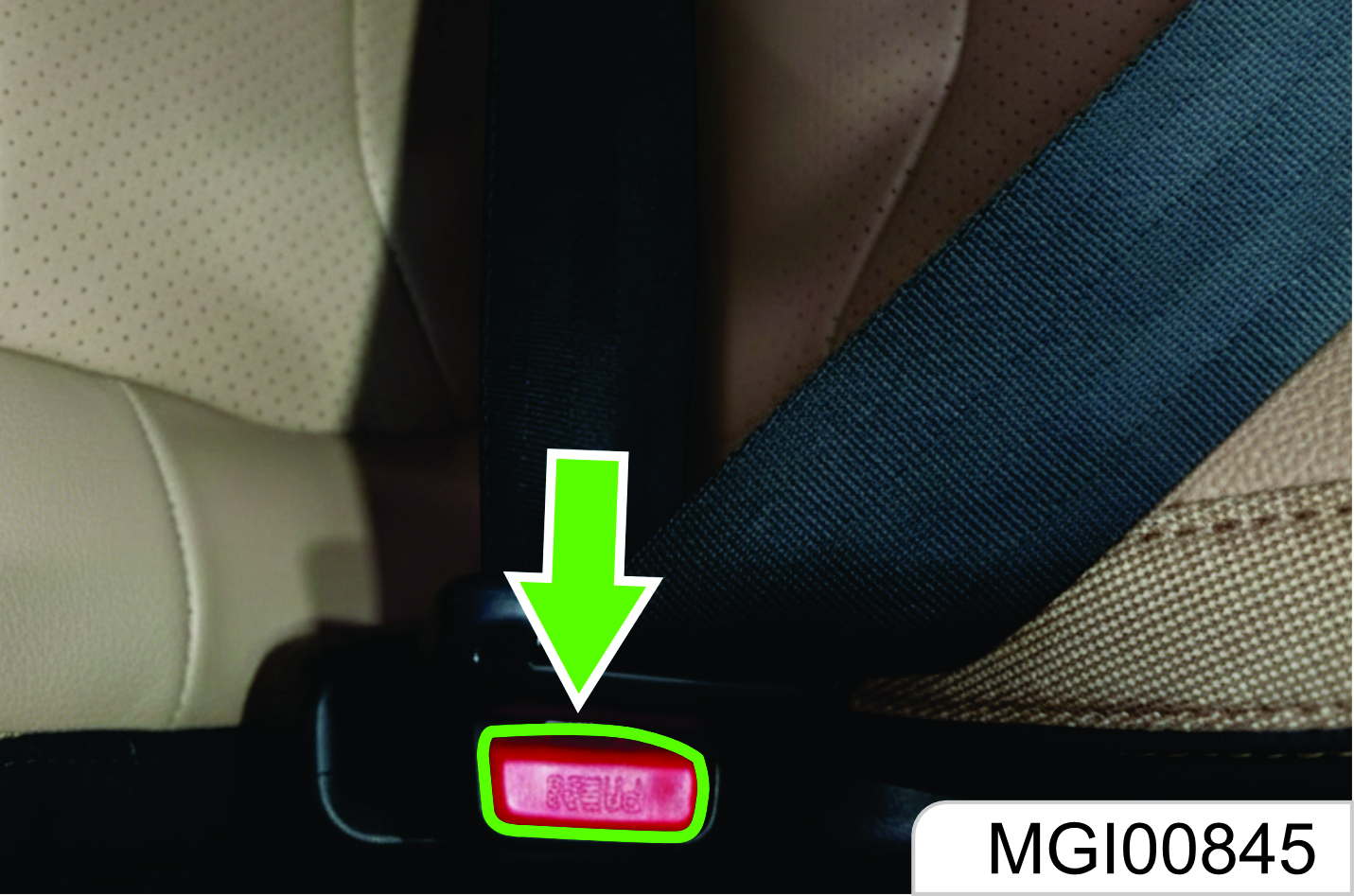
To unbuckle the seat belt, please press the red button on the buckle.
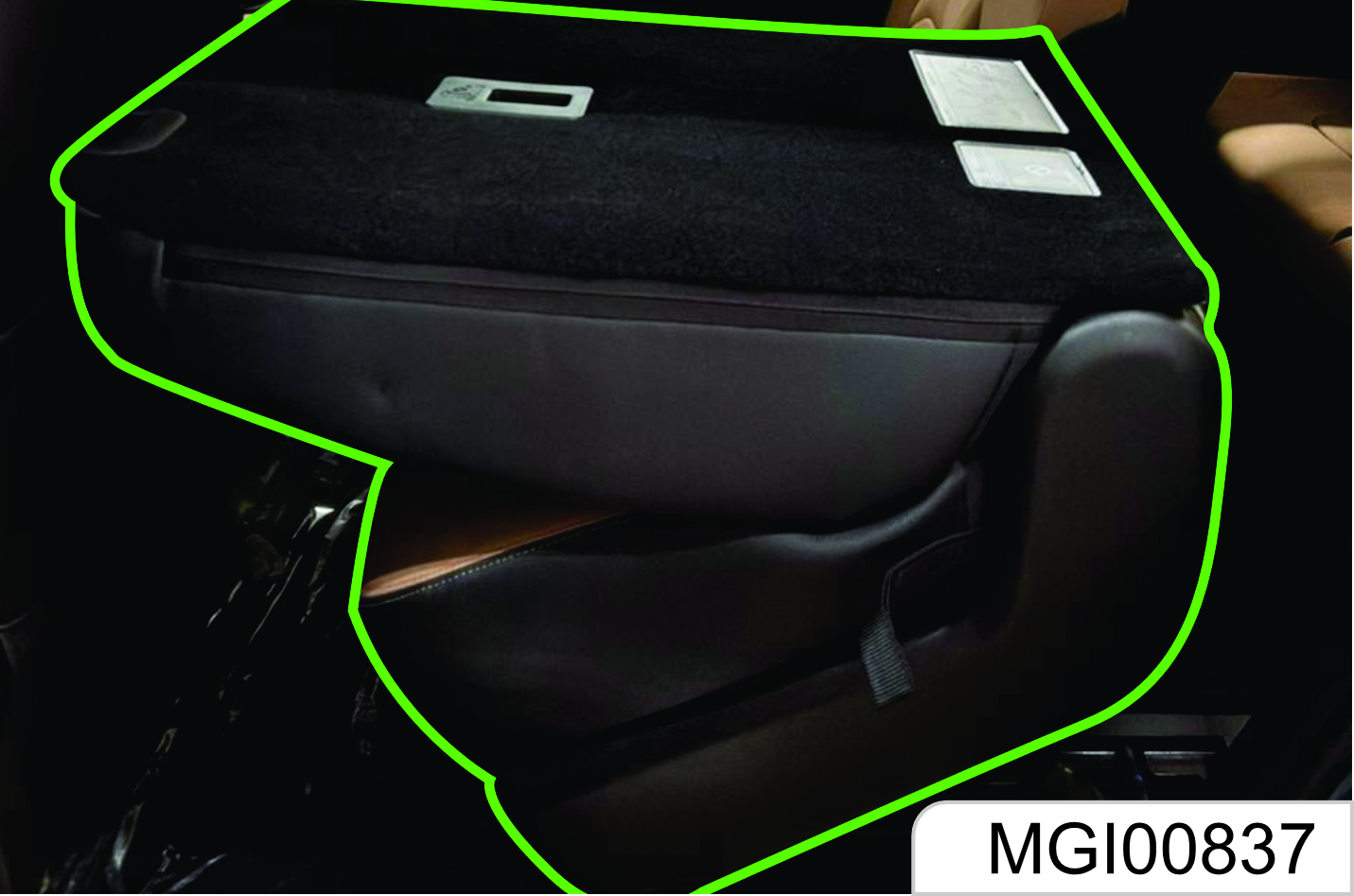
Middle Row / Rear Row Seat Belt Left and Right Seat Belt
For buckling and unbuckling of the left and right seat belts of the rear row, please refer to that of the front seat belt.
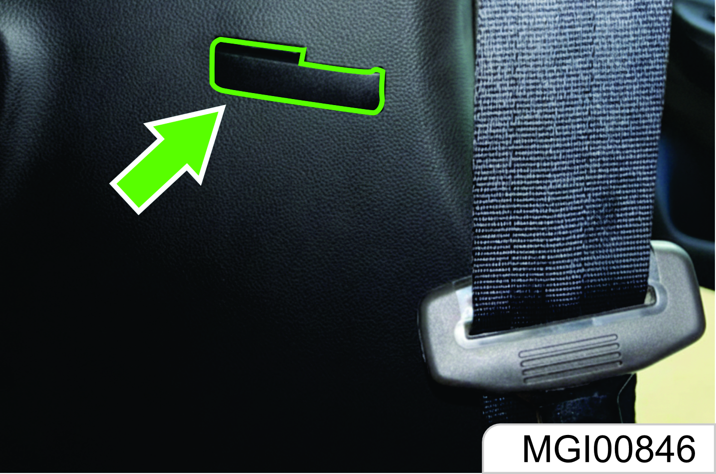
As shown in the figure, there is a clip on the trim panel near the second row seat backrest. Please hang the seat belt to the clip for fixing each time after use.
Middle Seat Belt of Rear Row
Wearing:
- Pull out the seat belt from the backrest first and sit well.
- Plug the latch plate at the seat belt end into the small buckle on the left side of the seat.
- Plug the other latch plate (movable) into the buckle on the right side of the seat.
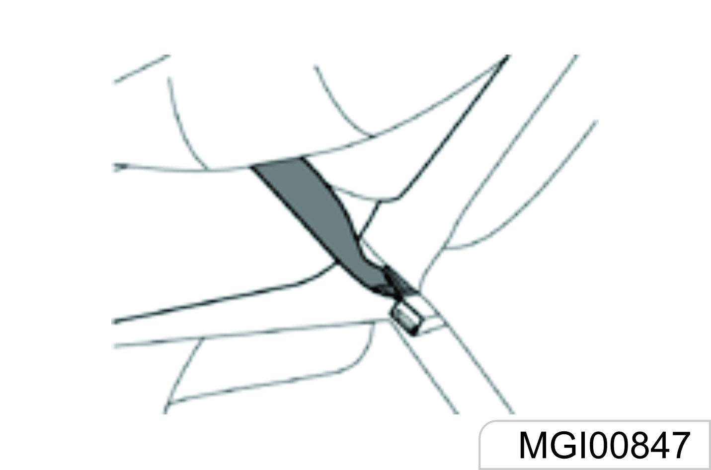
Seat Belt Use during Pregnancy
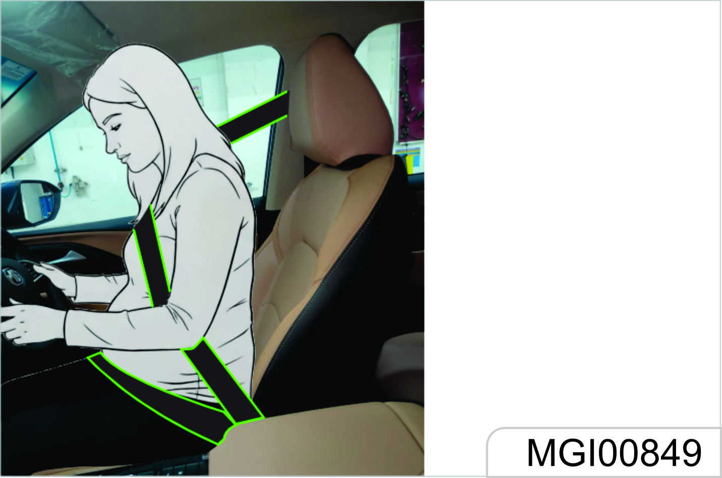
The seat belt provides protection for everybody, including a pregnant woman. Like all passengers, if pregnant women do not wear the seat belt, severe personal injuries are more likely to be caused to them. The pregnant woman shall wear the hip/shoulder seat belt during the whole pregnancy, and the hip belt shall be fastened as low as possible. The best way to protect a fetus is to provide safety protection to its mother. If the seat belt is fastened correctly, the fetus is not vulnerable to injury in case of a collision. For a pregnant woman or any person, correct wearing is the key to exert the best protection effect of the seat belt.
The hip belt shall be placed as low as possible to go across the pelvis, so as avoid force on the belly.
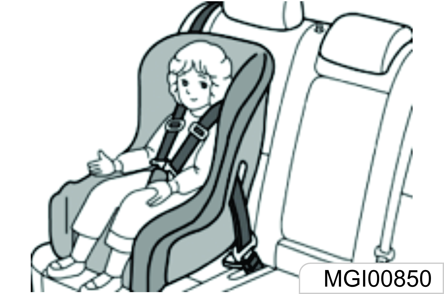
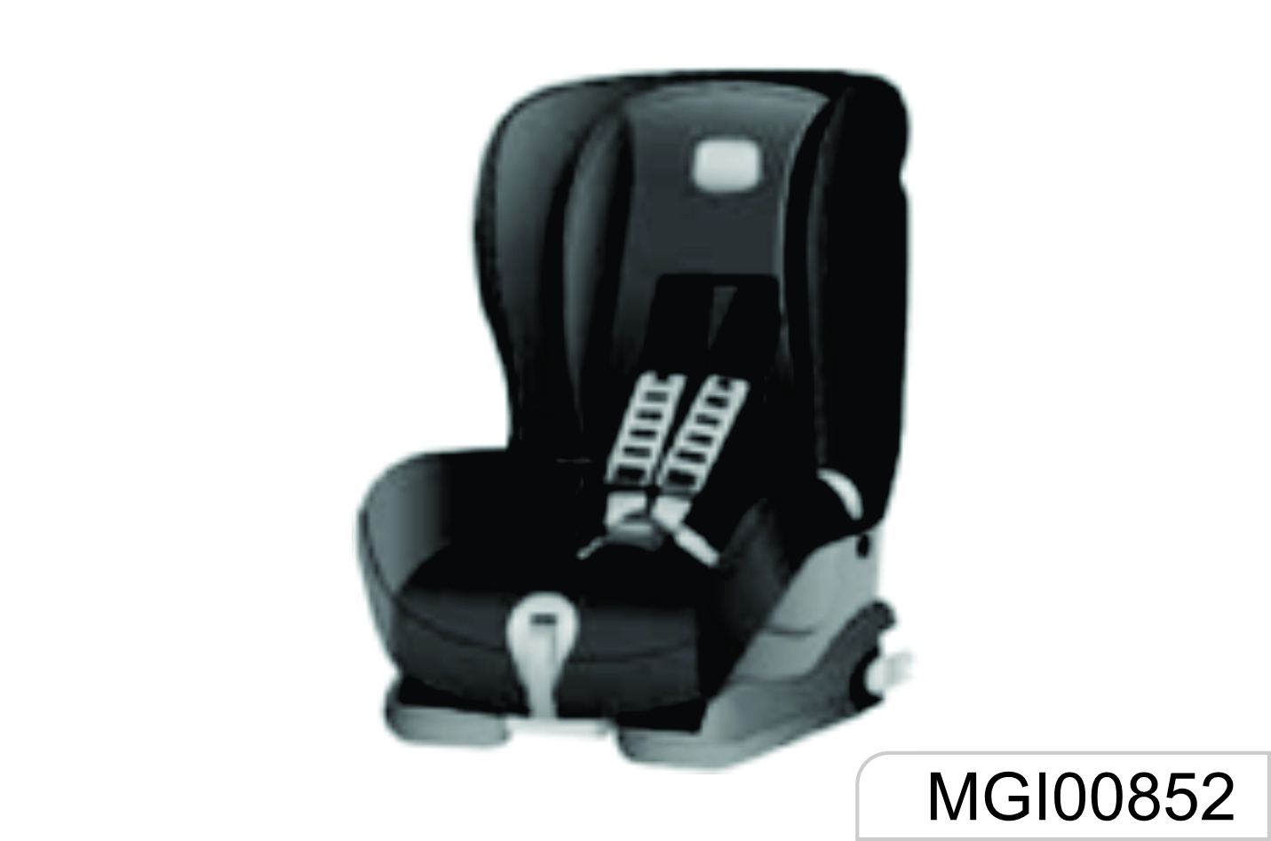
1.5 Child Seat
The vehicle is not equipped with a child seat. If you want to add one, a child seat that is applicable to ISOFIX "general" type can be selected. The child seat can only be placed on the second-row seat. The front seat is not equipped with the anchor system bracket. The statistical data of accidents show that placing the child seat on the second-row seat can largely improve the child safety
For a little child, a child seat shall always be used. Never hold a child with arms while riding in the vehicle. Never allow a child to stand or kneel on a seat or in the luggage compartment when the vehicle is running.
An unfixed child seat may be thrown out of the vehicle in case of a collision or emergency stop. The child seat must be correctly and securely fixed even if not in use.
If the child seat is put in a closed compartment in hot weather, the child seat temperature will be very high. Make sure that the child seat temperature is not very high before putting a child in the seat. If the child is too small and the seat belt cannot provide the best protection for it, please make sure that a proper child seat is used to provide safety protection.
Child Restraint System Type
According to AIS072/ECE R44, the child restraint system can be classified as the following 5 groups:
Group 0: for child with body weight less than 10 kg.
Group 0+:for child with body weight less than 13 kg.
Group I:for child with body weight more than 9 kg and less than 13 kg.
Group II:for child with body weight more than 15 kg and less than 25 kg.
Group III:for child with body weight more than 22 kg and less than 36 kg.
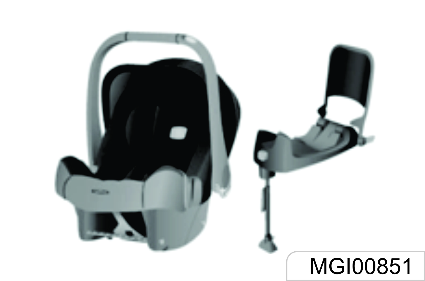
Please select a suitable child seat according to the child body weight and body structure.
For infants under one year old, their bones are very fragile, and a rearwardfacing child seat shall be used.
ISOFIX
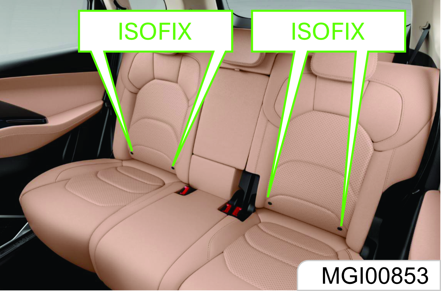
To fix the child seat:
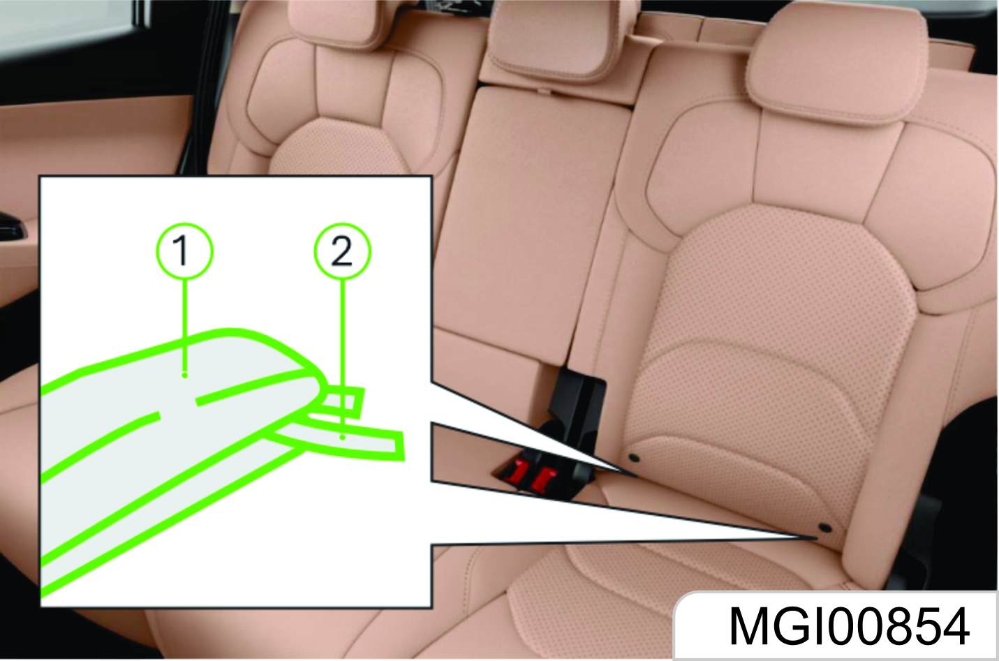
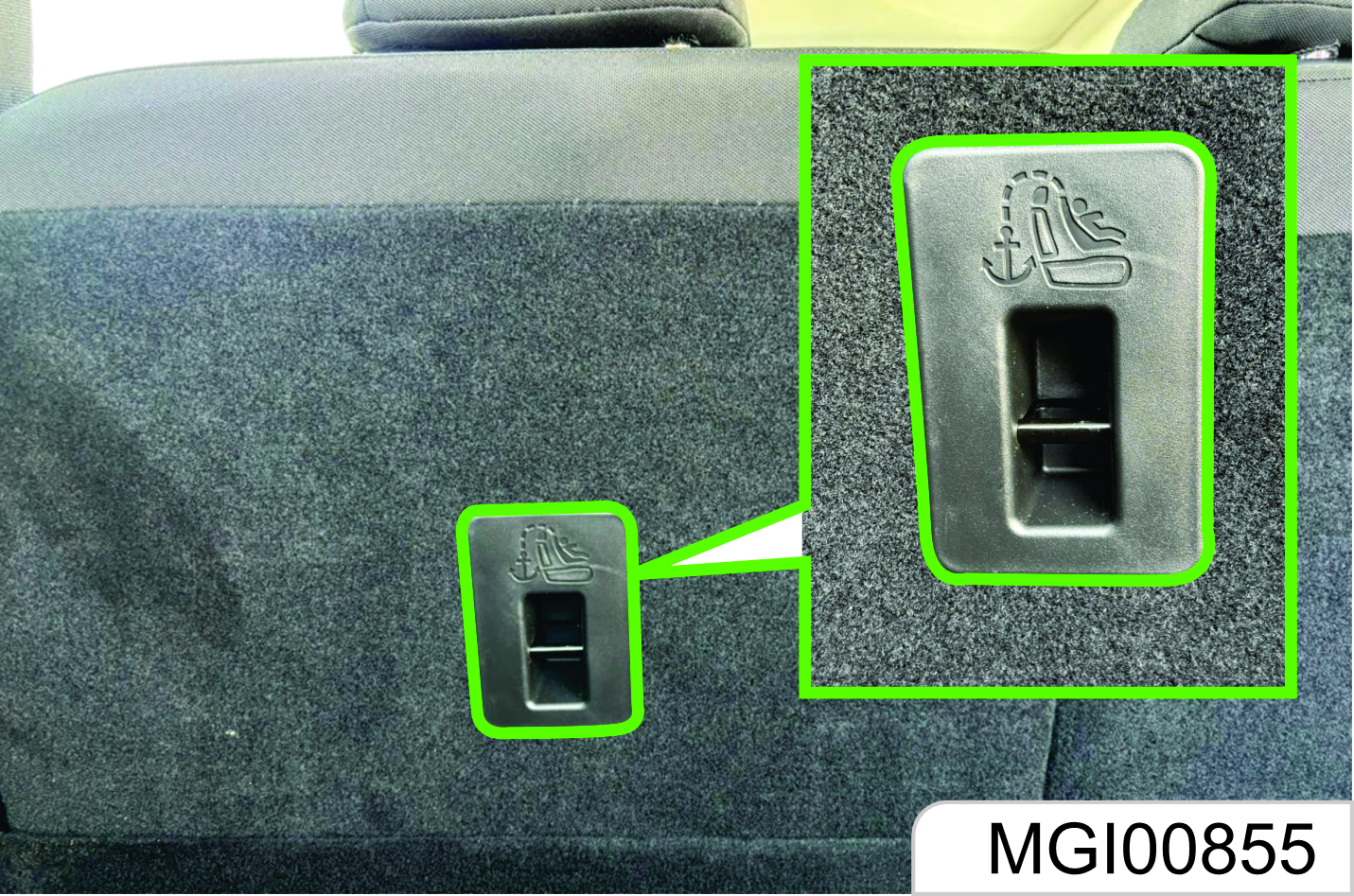
- The ISOFIX lower fixing point is on the joint between the second row set backrest and the seat cushion back. Its position can be identified through the label on the lower edge of the backrest. The left and right seats are equipped with a set of ISOFIX respectively.
- Clear up the objects on the seat. Note to remove the seat belt and seat belt buckle to avoid affecting accurate fixing of the child seat.
- Put the child seat on the secondrow seat.
The size and configuration range of the child seat is very wide. Not all child seats are applicable to your vehicle due to the effects of the vehicle trim as well as the seat shape and size . It's your responsibility to ensure that the child seat installed matches with your vehicle and that the child seat can be connected correctly to the vehicle with the child seat anchor system. If the child seat does not match with your vehicle size and the child body structure or the connection to your vehicle is incorrect, severe personal injuries can be caused to the child and other passengers in the vehicle in case of a collision.
- Connect the fixing caliper on the child seat to the on-vehicle fixing device. Operate according to the child seat instructions.
- Connect the upper strap of the child seat to the corresponding fixing point of the vehicle. Refer to the child seat instructions to get to know when and how to strain the upper strap. As shown in the figure, the ISOFIX upper fixing point is on the roof above the rear seat. Open the outer cover from the upper edge.
- Push and pull the child seat in all directions to make sure it is safely secured.
- Make sure that the child seat temperature is not very high before putting a child in the seat.
In case of a serious collision accident, the ISOFIX may be damaged. It may be necessary to repair and replace some parts. Please check the ISOFIX after a collision.
| Mass Group | Seating position (or other site) | ||||
|---|---|---|---|---|---|
| Front Passenger | Front Passenger | Rear Centre | Intermediate Outboard | Intermediate Center | |
| Group 0 up to 10 kg | X | U | NA | NA | NA |
| Group 0+ up to 13 kg | X | U | NA | NA | NA |
| Group I 9 to 18 kg | UF | U | NA | NA | NA |
| Group II 15 to 25 kg | UF | U | NA | NA | NA |
| Group III 22 to 36 kg | UF | U | NA | NA | NA |
|
Key of letters and their description: U = Suitable for "universal" category restraints approved for use in this mass group UF = Suitable for forward-facing "universal" category restraints approved for use in this mass group L = Suitable for child restraints given on the attached list. These restraints may be of the "specific vehicle", "restricted" or "semi universal" categories. B = Built-in restraint approved for this mass group. X = Seat position not suitable for children in this mass group. |
|||||
- As indicated above only Rear RH seat is recommended for CRS using Adult Safety Belt. (In case ISOFIX is not used)
- We only recommend using Universal Category ISOFIX seats for Children in recommended positions. (In case of ISOFIX CRS with latch & Top Tether, both left and right position may be used)
1.6 Air Bag System
Depending on the vehicle configuration, the system includes the following air bags:
- Driver frontal air bag
- Front passenger frontal air bag. (If equipped)
- Front seat side air bag. (If equipped)
- Side curtain air bag (if equipped)
For all air bags, the letter "AIRBAG" is marked on the trim panel or the label near to its deployment opening. For frontal air bags, the letter "AIRBAG" for the driver is located in the middle of the steering wheel, and that for the front passenger is located on the Dashboard near instrument panel. For lateralimpact air bags, the letter "AIRBAG" is located on the backrest side, near to the door. The letter "AIRBAG" for side curtain air bags is located on the roof lining trim panel.
An airbag provides supplementary protection when the seat belt is worn correctly. Although nowadays the air bags are designed to reduce the injury risks caused by the impact of force when the air bag is inflated, all air bags must be inflated rapidly to exert its effect.
The important notes about the air bag system are as follows:
Even if an air bag is equipped, you may also be injured seriously or lose your life in a collision accident if you do no use the seat belt. The air bag is designed to be used along with the seat belt but not to replace the seat belt.
If an occupant sits next to or get too close to the air bag, he/she may be injured seriously or lose life due to inflating of the air bag. Therefore, never sit too close to the air bag.
It is forbidden to let a child, infant, pregnant woman and the sick and weak person sit on the front seat equipped with air bag. Never install a backward- facing child seat on the front seat for the child may be injured seriously or lose life when the air bag is inflated. The seat belt and air bag can protect adults and adolescents but not children and infants. Children and infants need special child protection devices (such as child seat) to get corresponding protection.
1.6.1 Air Bag Indicator

On the instrument panel, there is an air bag indicator which displays the air bag shape symbol. The system will check whether the air bag circuit system has a fault and give corresponding prompt through the indicator. Refer to the Chapter "Instruments and Controls" for detailed information.
1.6.2 Air Bag Position
Frontal Air Bag
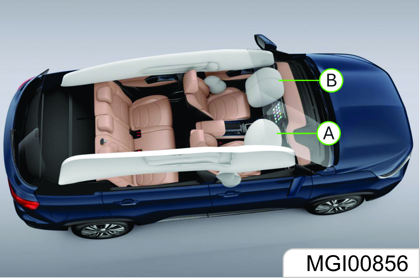
As shown in Figure A, the driver frontal air bag is located in the middle of the steering wheel.
As shown in the Figure B, the front passenger frontal air bag is located in the passenger’s side instrument panel.
Front Seat Side Air Bag*
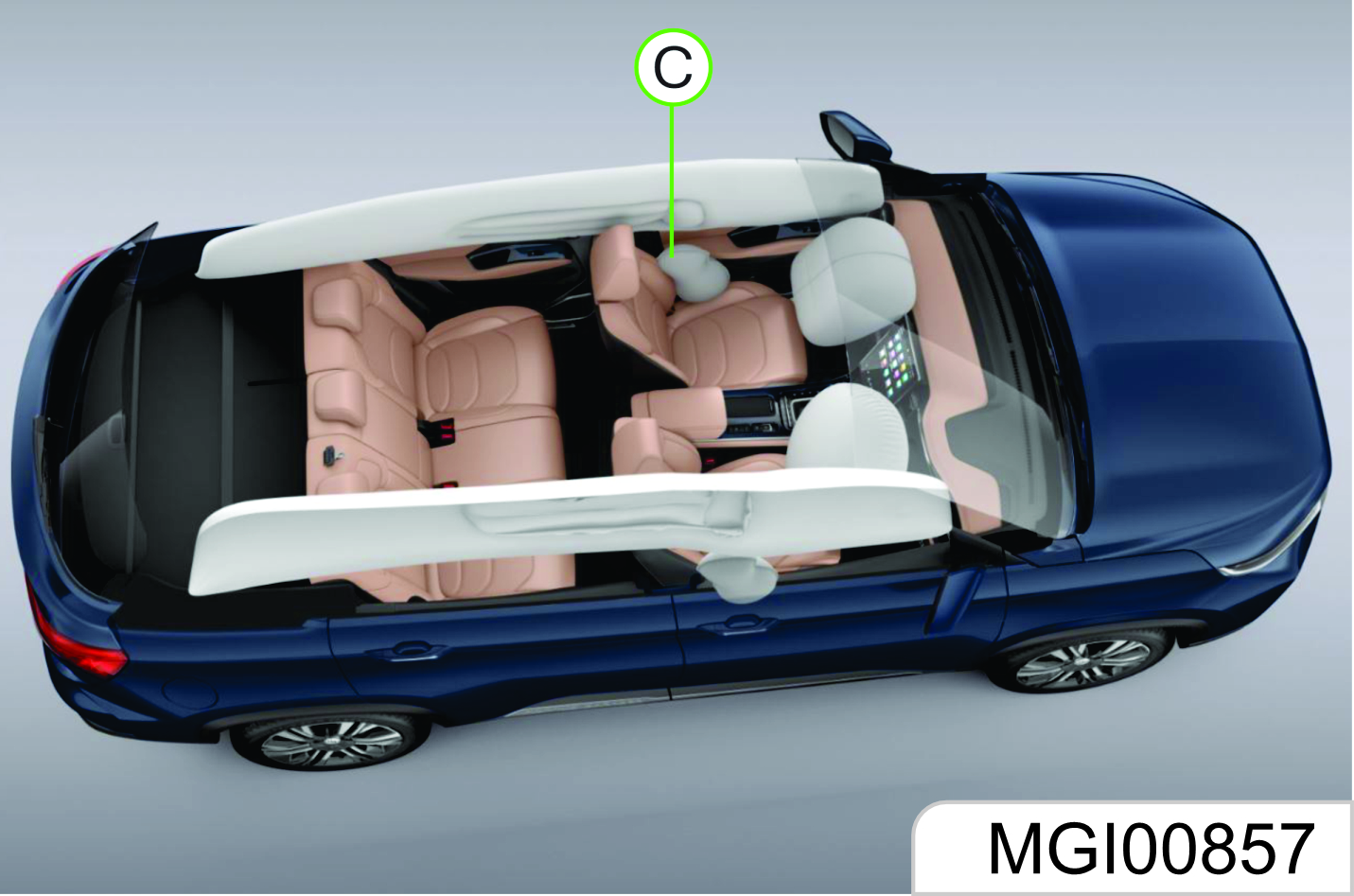
As shown in the Figure C, the front seat side air bag is installed on the backrest side near to the door.
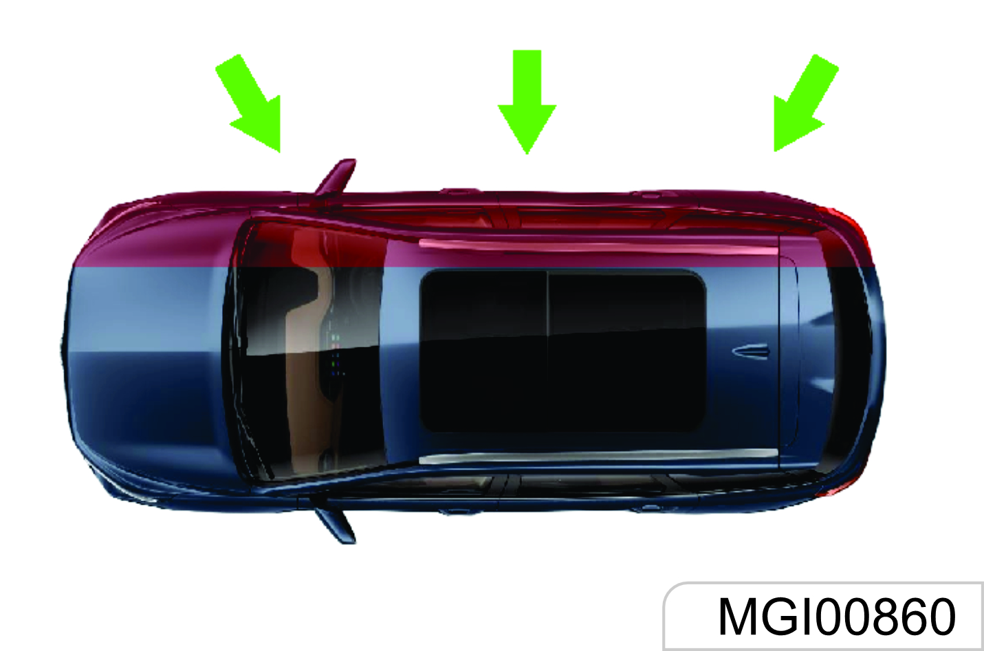
Side Curtain Air Bag
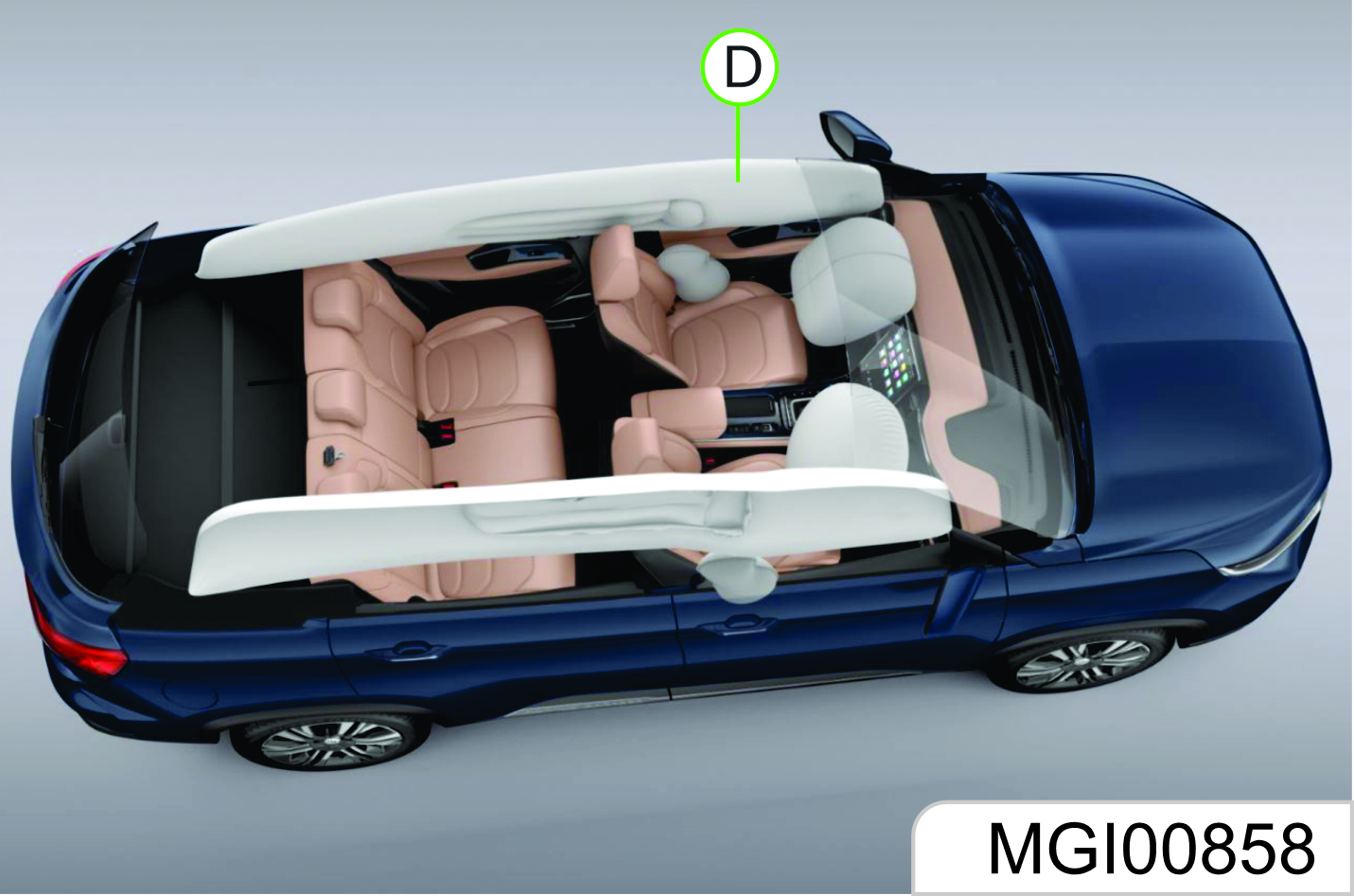
As shown in the Figure D, the side curtain air bag is installed at the side wall and roof joint, on the roof lining or the trim panel.
If there is any other object between the occupant and the air bag, the air bag may not be able to be inflated normally or the air bag may cause the object to squeeze the occupant*s body when it is inflated, leading to severe injuries or even death. Please never use a seat accessory (such as seat jacket) that may hinder the inflating of the lateral-impact air bag.
When Shall the Air Bag Be Inflated?
The frontal air bag is designed to be inflated in moderate to severe head-on collision or almost head-on collision to reduce severe injury risks of the driver’s and the front passenger’s head and chest.
Whether the frontal air bag is inflated do not mainly depends on the vehicle running speed. It depends on the impacted object, impact direction and vehicle deceleration within unit time during collision.
The frontal air bag may be inflated in different collision speed. The air bag inflation depends on the impact direction (straight or in certain angle) at the moment of collision and whether the impacted object is fixed or movable, deformable or not and narrow or wide. Due to different design of each vehicle, the collision inflation conditions of the frontal air bag may vary. The frontal air bag will not be inflated in case of vehicle overturn, rear-end collisions and most lateral-impact collisions.
The frontal air bag may not be inflated in slight headon or nearly head-on collisions, lateral or diagonal collisions, collisions to cylindrical objects (such as telegraph pole and tree trunk), rear-end collisions under large vehicle (trucks, etc.) and lateral glancing collisions. As per the design, the seat lateral-impact air bag and the side curtain air bag will be inflated according to the impact position in case of the moderate to severe lateral collisions.
The seat lateral-impact air bag and the side curtain air bag will not be inflated in case of head-on collisions, nearly head-on collisions, vehicle overturn or rear-end collisions. The seat lateralimpact air bag and the side curtain air bag may not be inflated in slight side collisions and lateral-frontal or diagonal collisions.
As per the design, the seat lateralimpact air bag and the side curtain air bag will be inflated on the side to which the vehicle is collided. The air bag will not be triggered in all collision accidents. For a particular accident, it shall not simply judge whether the air bag should be inflated according to the causalities, vehicle damage or repair and maintenance expenses. Your vehicle is equipped with a collision sensing and diagnosis module. If a collision accident reaches certain strength, the module may record relevant collision information after the collision. If you have any doubt on the working situation of your air bag in a collision accident, please contact the JSW MG Authorised Service Center timely to provide professional analysis and diagnosis for you.
How is the Air Bag Inflated?
In the inflation process, the sensing system will send an electronic signal to trigger the gas generator; the generator will release gas to inflate the air bag and to make the air bag pops up from the cover plate. The gas generator, air bag and relevant members are all components of the air bag module.
How Does the Air Bag Provide Protection?
The air bag supplements protection provided by the seat belt by distributing the impact force more evenly to the occupant’s body. However, some occupants’ bodies do not move toward the air bags in collisions where an external object intrudes into the vehicle. The air bag cannot provide corresponding protection. The air bag shall only be deemed as a supplementary device of the seat belt.
What Will You See After the Air Bag is Inflated?
After the air bag is inflated, it will be deflated quickly. Somebody may not note that the air bag is ever inflated because the bleeding speed is very fast. For deflated air bag, some smoke and dust may come out from its air event.
When the air bag is inflated, there may be dust spread in the air. All persons in the vehicle shall get off the vehicle as soon as possible. If you have a breathing problem and cannot get off the vehicle, open windows or doors to get fresh air. If you have a breathing problem after the air bag is inflated, please see a doctor as soon as possible.
If the vehicle power supply system can still function normally after a collision, the vehicle has the functions of unlocking doors automatically, turning on the hazard warning lamp and cutting off the fuel system after the air bag is inflated. The driver can use the corresponding function switch to lock doors, turn off indoors lamps and turn off the hazard warning lamp.
The deployment of the front passenger air bag may also cause damage to the windshield.
The air bag can only be inflated once as per its design. After the air bag is inflated, some parts of the air bag system need to be replaced. If you do not have these parts replaced, the air bag system will be unable to provide protection in next collision accident. The air bag system parts that shall be replaced include the air bag module, air bag control module, seat belt pretensioner and other parts.
- Work related to the air bag system can only be done by technicians with corresponding qualification. Improper repair and maintenance may cause that the air bag system cannot function normally. Please drive to the MG Authorised Service Centre for repair and maintenance.
Air Bag System Repair, Maintenance and Replacement
The air bag system must be maintained by qualified professional technicians. Improper maintenance will cause that the air bag system cannot function normally. Please drive to the JSW MG Authorized Service Center for repair and maintenance of the air bag system.
If the air bag cover is damaged, opened or broken, the air bag may not function normally. 1t shall be repaired as soon as possible.
Never stick or cover any object on the air bag cover surface or refit the air bag cover; never try to repair, adjust or remove or install any air bag system component; never try to refit the front bumper of the vehicle body by yourself.
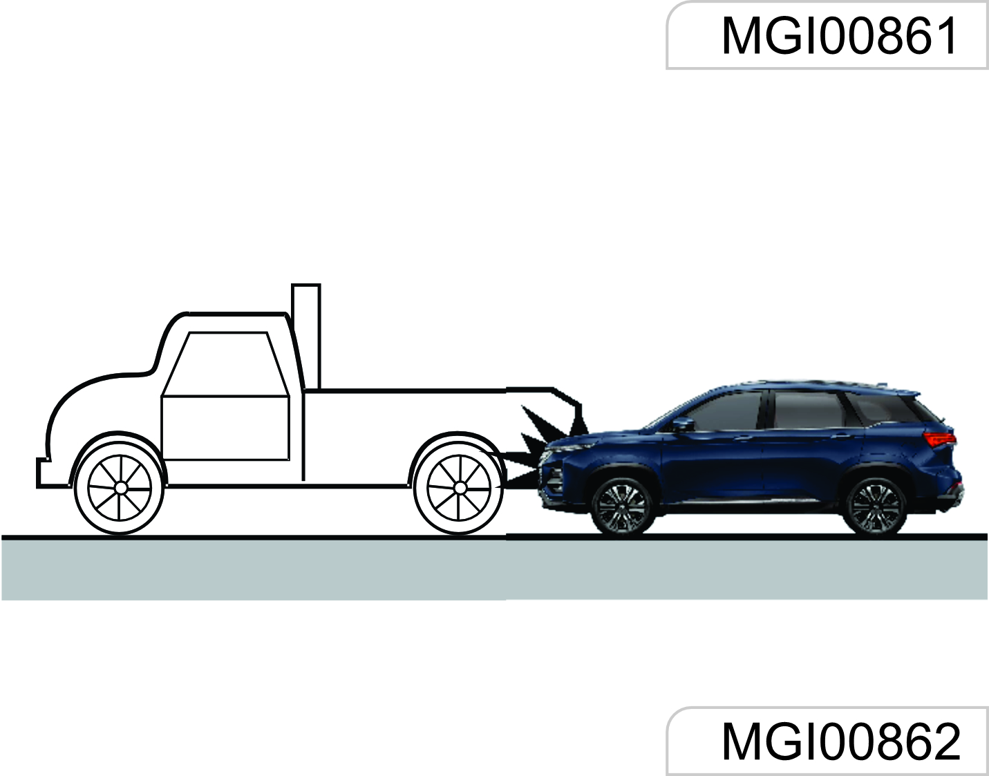
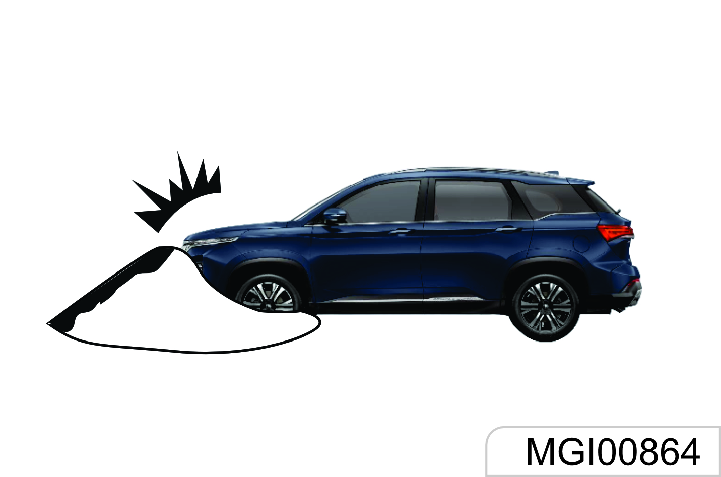
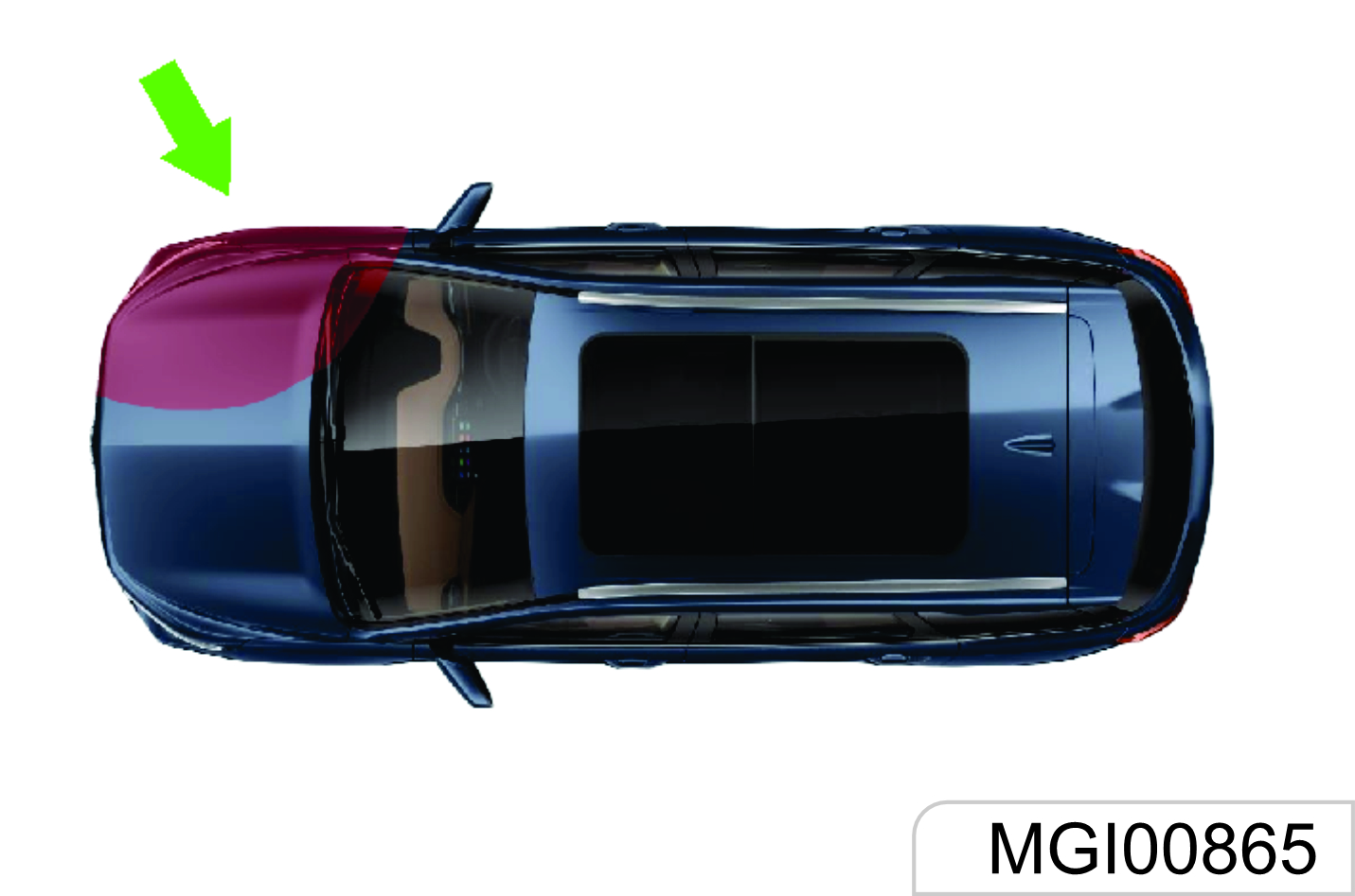
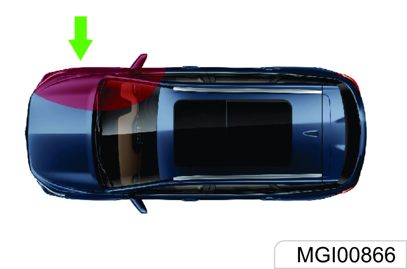
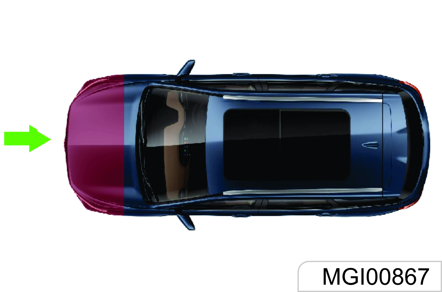
The Frontal Air Bag May Not Be Inflated in the Following Collisions
The frontal air bag will usually not be inflated in case of side collisions, rear-end collisions, turnover or lowspeed head-on collisions. No matter what kind of collision, only when the vehicle generates sufficient forward deceleration, will the frontal air bag be inflated.
Head-on collision angle over 30° from vehicle longitudinal direction
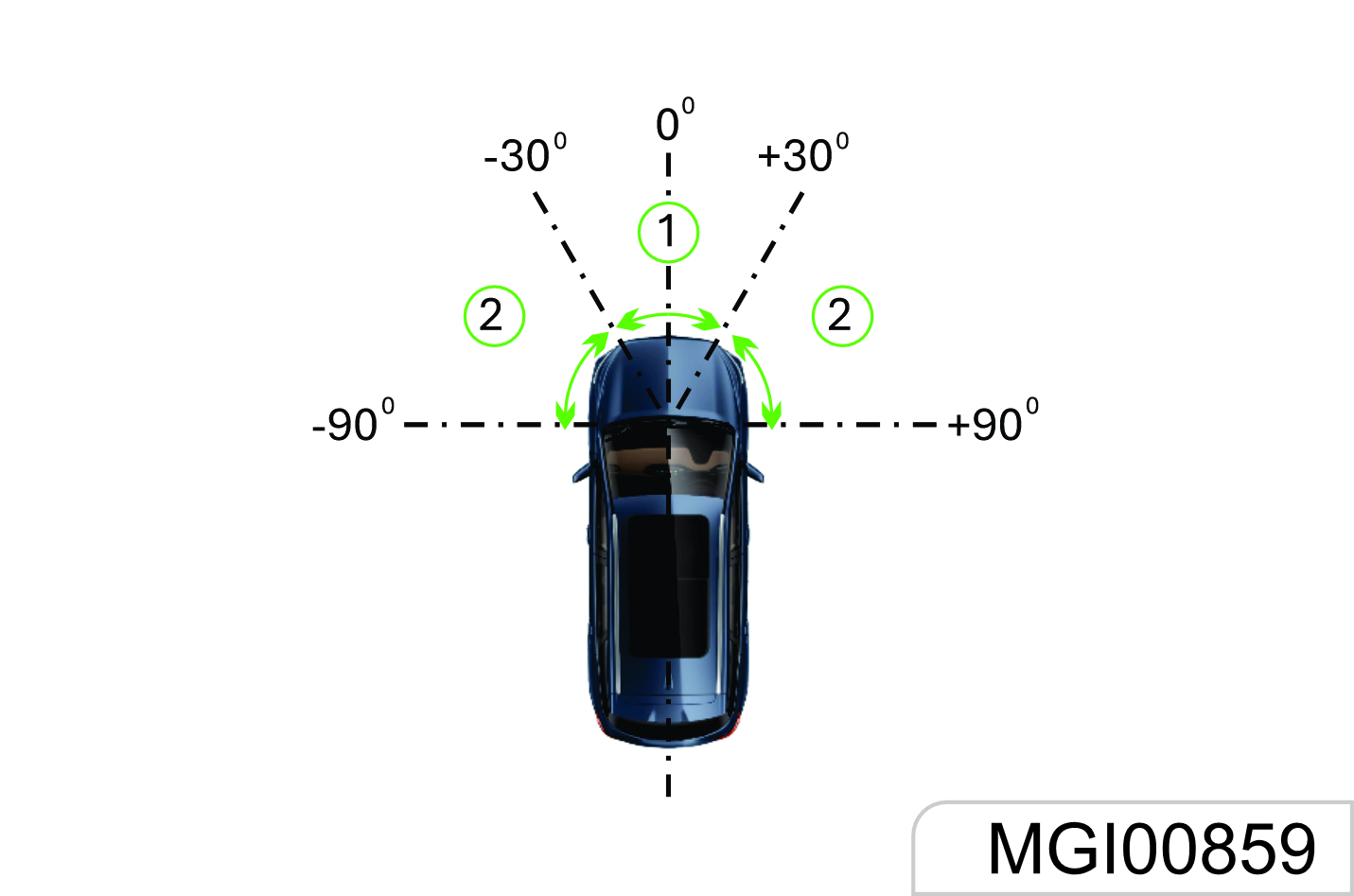
Side collision
Overturn, falling from high place, rolling

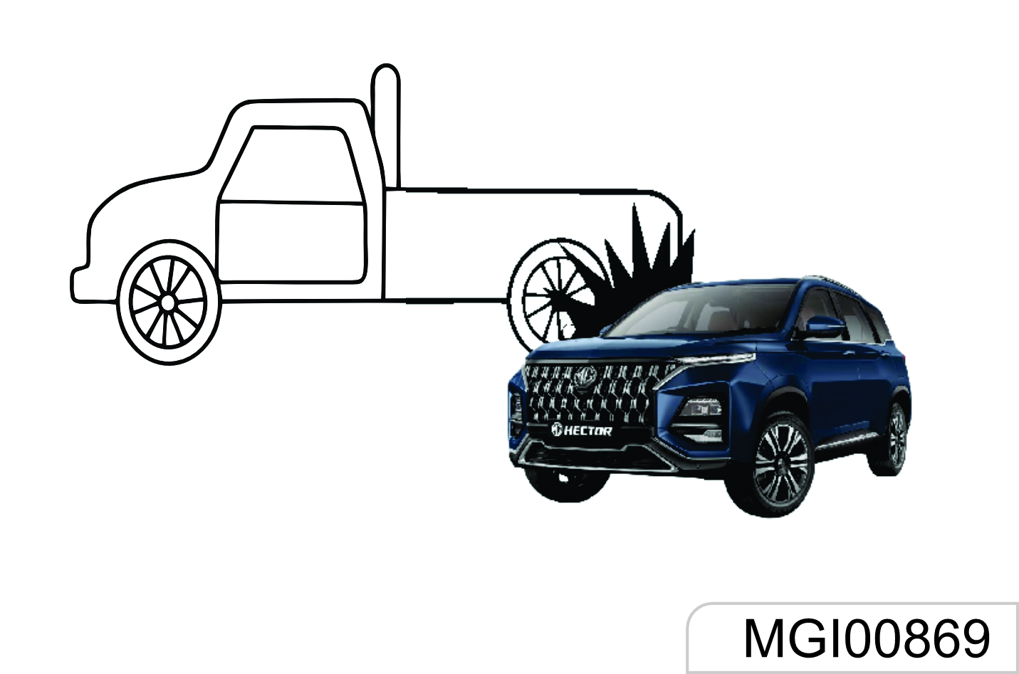
Hit into front vehicle bottom, especially truck bottom
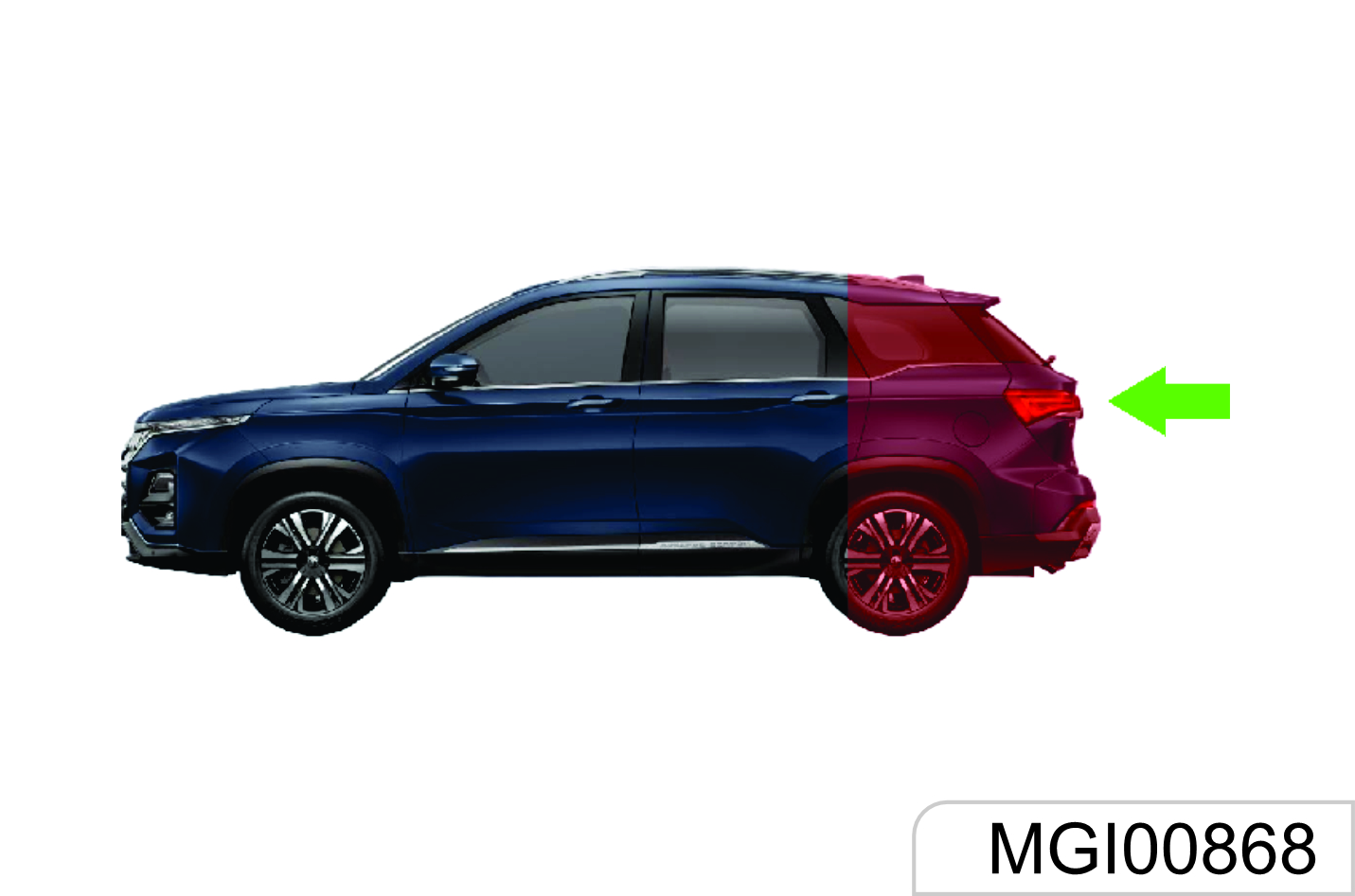
Rear-end collision

Hit deformable objects, such as sandpile, guard bar, column and tree
Side Air Bag / Side Curtain Air Bag (If Equipped) may not be inflated in the following collisions. In case of side collisions with certain angle or collisions to vehicle body side (not passenger compartment), the side air bag/side curtain air bag system may not be activated.
Vehicle body side (not passenger compartment) collision
Off- vertical side collision
The side air bag/side curtain air bag will usually not be inflated in case of head-on collision, rear- end collisions, overturn or low-speed side collisions.
Fall into or drive into a deep pit
Head-on collision
Rear-end collision
Side collision to truck during drifting
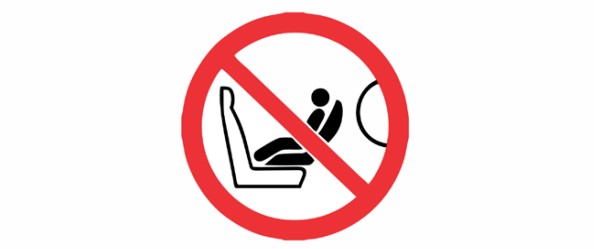
Do not use a backward-facing child restraint system on a seat (front seat) protected by a frontal air bag (in activated state). Otherwise, severe injuries or even death may be caused to the child when the air bag is deployed.
Overturn, falling from high place, rolling
1.7 Braking System
The brake system is designed for the braking performance under the driving conditions in wide range. In the braking process, the vehicle speed is reduced through the braking friction and the friction between tyres and ground. It is normal that small braking friction sounds, and friction sounds between tyres and ground are given with no need for special treatment. It is also normal that occasional squeals are given in braking. Squeals may be produced for such causes that other matters may adhere to the friction faces during operation of the vehicle, the vehicle is out of operation for a long time, or friction faces get rusted after raining. As long as squeals are produced at a lower frequency, there is no need for special treatment.
To avoid the pedal travel from being influenced, do not lay a thick carpet in the brake pedal area.
If you find that the brake pedal fails to return or the brake pedal travel becomes longer, we strongly advise you to have your vehicle inspected at the JSW MG Authorised Service Centre. This may indicate a faulty brake system.
When you drive your vehicle in one high- altitude area, continuously braking may cause the brake pedal force to increase.
To run in the friction plate and the brake disc and confirm the performance and the service life, after purchasing a vehicle and installing new friction plates, you should better avoid emergency braking or braking for a long time with in milage of 200 km.
Please check whether the brake lamp is normal before driving your vehicle. Keep the vehicle running at low speed after starting the vehicle, and check the braking performance. You shall do more like this especially after your vehicle is just washed.
The wet brake may cause an accident. In case the brake is wet, the brake fails to function well and thus the vehicle may get out of control due to lateral deviation. Therefore, after driving through water or having your vehicle cleaned, keep the vehicle running at low speed and depress the brake pedal intermittently and gently, so as to dry the brake.
If the brake is unable to function temporarily due to overheat.
Engage a lower gear when driving downhill and use the engine to brake.
If the brake is unable to function temporarily due to wet components, the normal performance can be recovered with the help of following procedures:
- Check whether there are vehicles behind your vehicle.
- Keep safe driving speed to ensure there is sufficient space at both (Front & Back) side of your vehicle.
- Carefully depress the brake till the normal performance is recovered.
Anti-lock Brake System (ABS)
As one advanced electric braking system, the anti-lock brake system (ABS) is helpful in avoiding the vehicle from slipping and losing control, and this system can also provide the maximum braking capability on the slipped pavement.
When the ignition switch is turned on, the ABS warning lamp illuminates momentarily. The ABS warning lamp does not go out or illuminates when the vehicle is running, it indicates that the ABS is faulty. Please immediately contact the JSW MG Authorised Service Center. Refer to "ABS Warning Lamp" under Chapter "Instrument and Control Device".
The ABS will monitor the speed of each wheel during braking. If one wheel tends to be locked, the system will control brakes of two front wheels and two rear wheels respectively. When the ABS works, the brake pedal often vibrates slightly with noise.
If the ABS gets faulted, it may be unable to function, wheels may be locked in case of emergency brake, and the vehicle may be unable to steer or may steer suddenly.
The ABS will neither change the time required for brake engagement, nor shorten the braking distance. Sufficient braking distance must be kept even the ABS is equipped.
Electric Brake Force Distribution (EBD) System
The EBD system uses the high-speed computer to respectively induce and calculate different ground to which four wheels are attached, and thus calculate different friction values at the moment the vehicle brakes. Therefore, four wheels can be able to brake in different ways and force based on different conditions, and can be adjusted fast during movement, so as to ensure that the vehicle is stable and safe.
Electronic Stability Control (ESC) System*
The ESC system is a new-type active safety system, representing the further development of the functions of antilock brake system (ABS) and traction control system (TCS). In addition, the yaw rate sensor, lateral acceleration sensor and steering wheel turn angle sensor are added. The driving force and braking force of front and rear, left and right wheels are controlled through the ECU, which ensures the lateral stability of the vehicle. When the driver operates the vehicle beyond the limit values, in case of turning at high speed, the ESC system automatically intervenes to ensure that the vehicle returns to be controllable and ensure the safety. Indicators relevant to the ESC system include ABS fault indicator, EBD fault indicator, ESC indicator and ESC OFF indicator.
- Indicators illuminate for selfinspect when the ignition is connected. The 4 indicators are normally on for 3s, indicating that the ESC system is conducting self-inspect and indicators work normally. The 4 indicators go out 3s later under the normal condition. When faults (such as neglected installation, loosened connector, abnormal CAN communication) exist on the ESC system, only the ESC OFF lamp will go out 3s later, and other 3 lamps are normally on.
- During driving, if the ESC function is activated, the ESC indicator will flicker, telling the Owner that the ESC system is working. If the ESC system functions abnormally but the ABS+EBD system functions normally, the ESC indicator is normally on, indicating that the ESC system gets faulted. If the ESC system and the ABS function abnormally but the EBD system functions normally, the ESC and ABS indicators are normally on. If the ESC system, the ABS and the EBD system function abnormally, the ESC, ABS and EBD indicators are normally on.
- The ESC OFF lamp is used to indicate that the ESC function is disabled (the lamp will be normally on so long as the ESC function is disabled; the lamp will go out if the function is enabled). If the user press the ESC OFF switch, some ESC functions will be disabled, and the ESC OFF lamp illuminates. When the switch is pressed, the ESC system is working, and the ESC function will not be disabled immediately and will be disabled after the work is over. If the user presses the ESC switch again, all functions will be enabled again. If the pressed time of ESC switch exceeds 10s, the ESC system will consider it as one incorrect operation (for example, the switch is pressed by one unknown article incautiously), the ESC function will not be disabled.
- The ESC system will be activated automatically after every ignition cycle.
The ESP system may not be able to help you escape from out-ofcontrol in the ultimate state for sure. Therefore, take care during daily driving.
You had better disable the ESP system when crossing country on a sandy and rocky pavement. As it is time for the ESP system to function on an icy, snowy and slippery pavement, the ESC system shall not be disabled.
ESC OFF Switch
Press the ESC OFF switch after starting the vehicle. The ESC OFF lamp on the instrument cluster turns on, and some ESC functions are disabled. Press the ESC switch again, the ESC function is enabled again and the ESC OFF indicator on the instrument cluster goes out.
Normally, it is not recommended to disable the ESC system. The system should be disabled temporarily only when the vehicle gets out of the mire or the vehicle climbs on a snowfield, etc.
Hill-start Hold Control (HHC) System *
The ESC system has the HHC function. The function can help the vehicle to start easily on a slope without using the parking brake.
Whether the driver is driving or reversing onto a hill, the start assistant is provided through the function. Therefore, engage gear before starting.
When the hill-start hold control functions, after the brake pedal is released, the vehicle still keeps the braking force for 1-2s. In this case, the vehicle will not slide backwards. For one MT vehicle, the driver can focus on engagement of accelerator and clutch in 2s, so as to deal with the tense hillstart with ease.
In this 2s, if the driving force applied by the driver is greater than the resistance which the vehicle is subject to when running onto a hill, the system will gradually reduce the braking force and the vehicle starts running smoothly. If the vehicle fails to start running in 2s, or the driving force applied by the driver is insufficient, the pressure of the brake system is released automatically and the vehicle may start sliding a slope.
At the time, you can depress the brake pedal to make the vehicle come to a complete stop, and the system will still help you to conduct the next start (when conditions are met).
Conditions for the HHC system to function:
- No fault exists on the system, and the engine has been operating;
- The vehicle is motionless and the brake pedal is depressed;
- The system detects that the gradient value is met. (In theory, when the slope is > 4%, the vehicle will nod during braking, and the nodding angle will offset the slope. As a result, the system may fail to be started on a ramp whose slope is > 4%.)
When the vehicle is reversed onto a slope, it is necessary to set to the reverse gear firstly.
The HHC function may fail to prevent the vehicle from sliding a slope on a very slippery or steep hillside.
Only as one driver-assistance measure, the HHC function cannot supersede the parking brake function.
Always Apply the parking brake when getting out of the vehicle. If there is no sufficient driving force provided after the brake pedal is released, the vehicle will slide backwards. In this case, please immediately draw back the parking brake and depress the brake pedal.
If the engine flames out during the process, please immediately draw back the parking brake and depress the brake pedal.
1.7.1 Parking Brake
Mechanical Hand Brake*
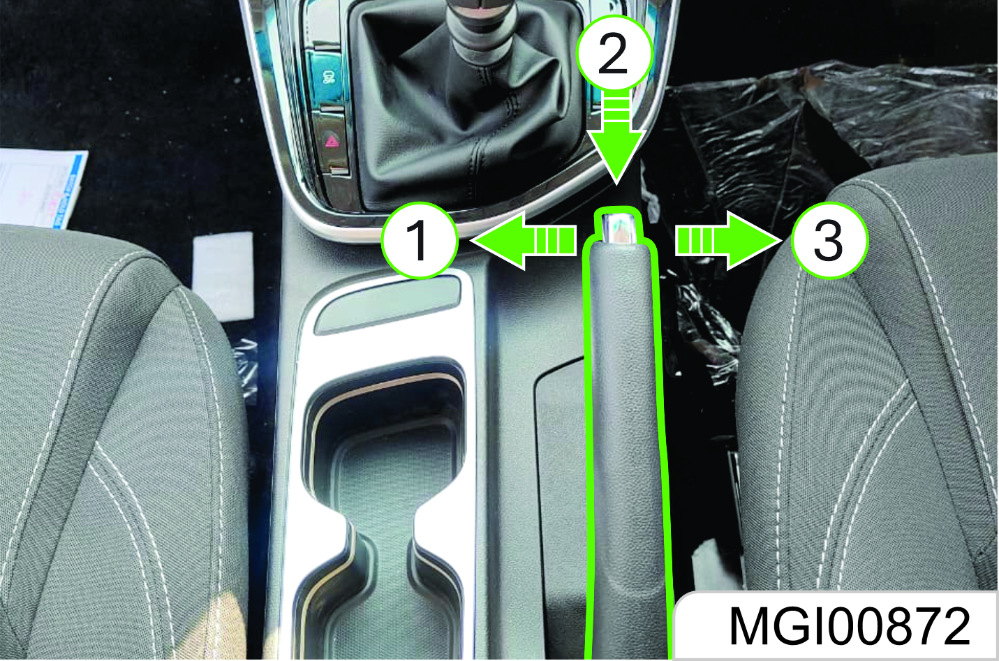
The parking brake impacts rear wheels.
The parking brake lever is between two front- row seats.
If you are to use the parking brake, you should stop the vehicle, depress the brake pedal and tension the parking brake lever.
When you are to release the parking brake, depress the brake pedal and take the following measures:
- Draw back the parking brake lever slightly.
- Press the button on the parking brake lever joint.
- Release the parking brake lever when holding the button pressed.
When parking the vehicle on one downhill ramp, turn the front wheels towards the road shoulder
Vehicle equipped with a manual transmission:
- Turn the gear lever to the neutral gear when parking the vehicle on the horizontal ground.
- Turn the gear lever to the reverse ® gear when parking the vehicle towards the downhill direction.
- Turn the gear lever to Gear 1 (turn the automatic transmission to Gear D) when parking the vehicle towards Gear D).
When parking an automatic model with Continuously Variable Transmission, engage Gear P on all pavements.
If the parking brake is not engaged correctly, the vehicle may move automatically due to out-of-control in some cases (such as in case of parking on a ramp) and thus a danger may be caused.
When necessary, please have the JSW MG Authorised Service Center adjust.
Do not drive the vehicle with the parking brake engaged; otherwise the rear wheel brake may get overheated or be subject to premature wear. As a result, you must replace the rear wheel brake; otherwise, other components of the vehicle may get damaged.
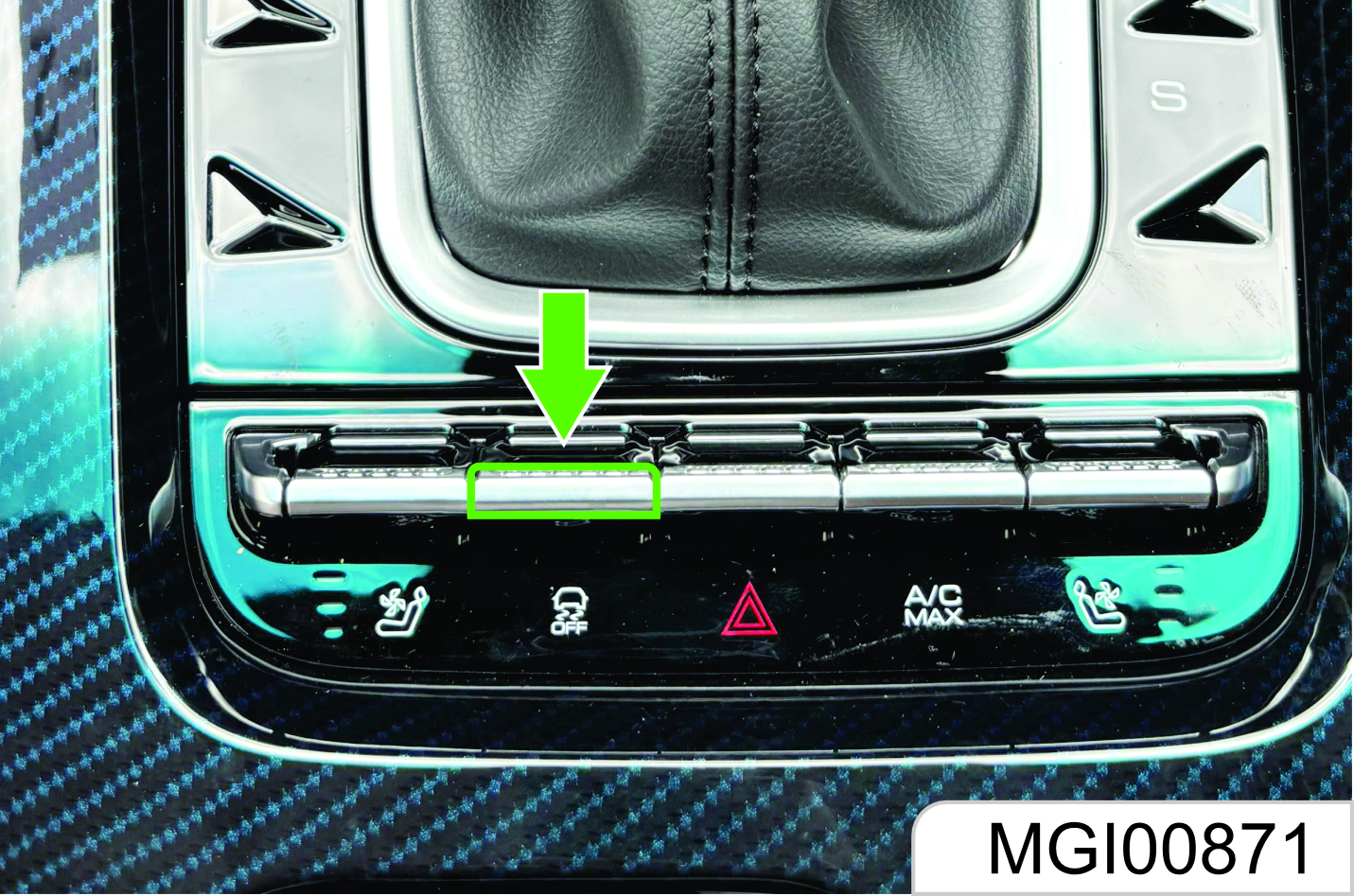
Electronic Parking Brake (EPB) *
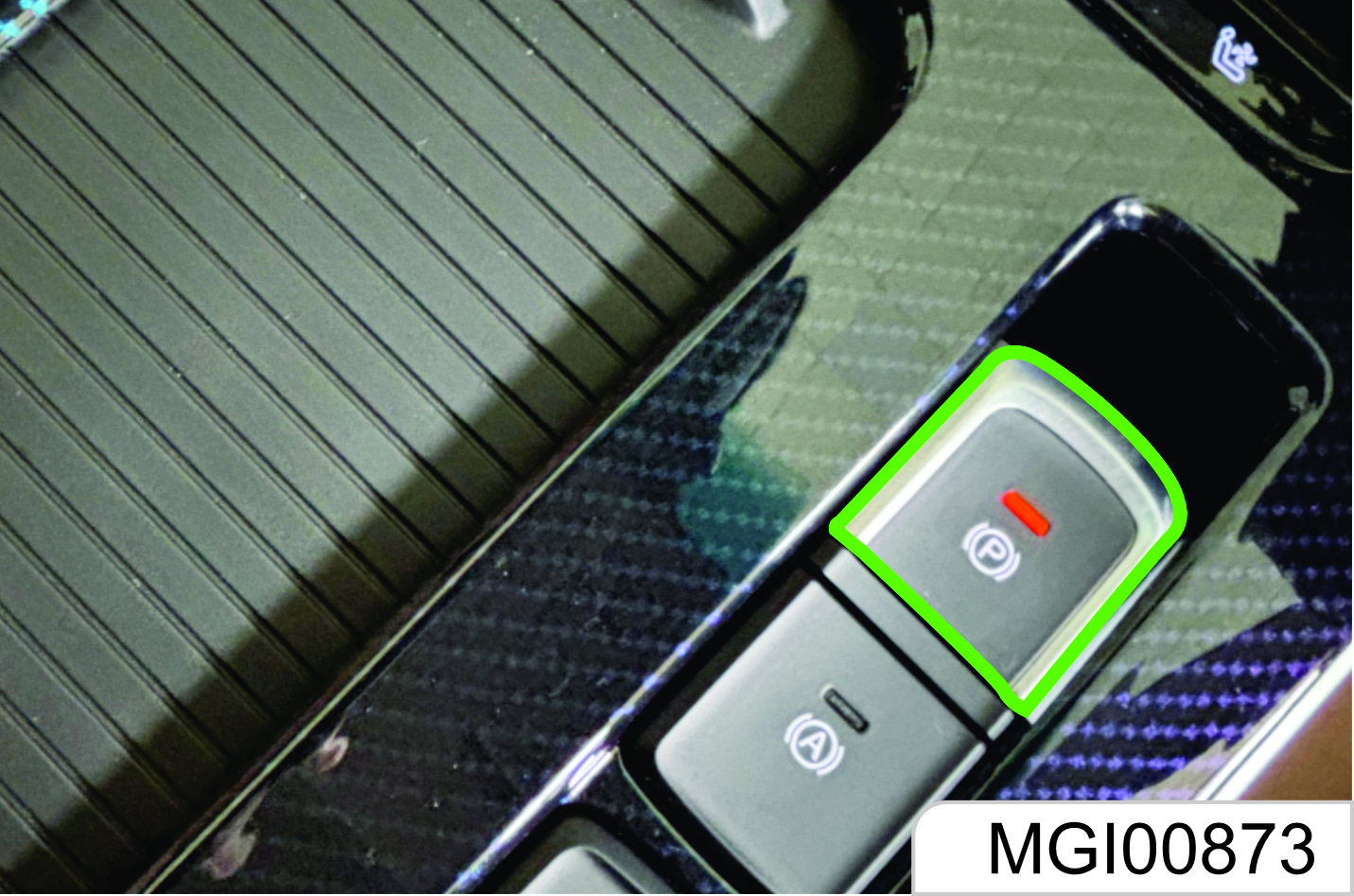
The parking brake impacts rear wheels.
As shown in the figure above, the EPB switch is between two front-row seats.
Manually Apply Parking Brake
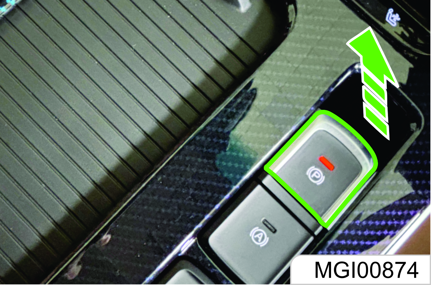
If you have to apply parking brake, depress the brake pedal to stop the vehicle and then draw back the electronic parking brake switch. In this case , the EPB working indicator illuminates, and you release the EPB switch after the instrument cluster displays "Parking brake applied"
At the time, the EPB system brake will be clamped to park the vehicle in situ.
In the process of applying or releasing the parking brake, it is normal that you will feel that the brake pedal lifts or lowers.
Manually Release Parking Brake
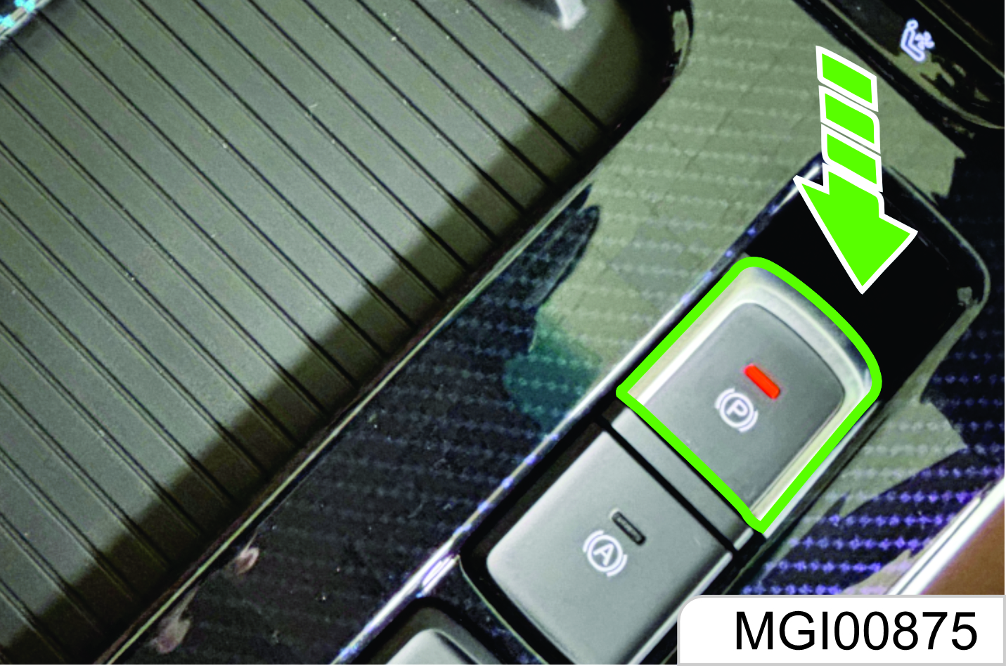
If you have to release parking brake, firstly confirm that the ignition switch is at the ON position, depress the brake pedal, and then press the EPB switch. The EPB working indicator goes out, and the instrument cluster displays "parking brake released", reminding you of parking brake released.
If the brake pedal has not been depressed, the instrument will give a hint "Please depress the brake pedal andthen release the EPB switch" and then when you are operating the EPB switch, the switch will make response only when the time for releasing or pressing the switch is > 0.1s.
EPB Automatic Clamping Function
When the engine flames out in the motionless state, the vehicle will automatically apply parking brake, and you do not have to pull up the EPB switch.
EPB Automatic Releasing Function
You do not have to manually release parking brake when starting the vehicle; parking brake will be released automatically when the system detects that the vehicle is going to start.
Start the vehicle, engage gear (drive gear or reverse gear), and the driver’s safety belt is tightened; depress the accelerator and release the clutch. After the vehicle start conditions are met, the parking brake will be released automatically.
To smoothly start and avoid sliding backwards on an uphill pavement, opening of the accelerator being depressed shall be enlarged properly
Anti-sliding Reclamping Function
When the parking brake is in the clamped state, if it is detected that wheels roll, EPB will immediately reclamp to avoid sliding.
EPB Hot Disc Reclamping Function
If you park when the rear brake disc temperature is high, the braking force may reduce after a period of time due to thermal expansion and cold contraction. EPB can keep the braking force by reclamping many times to avoid sliding.
EPB Dynamic Braking Function
During driving (speed > 3 km/h), continuously draw back the EPB switch to trigger the ESC system so as to brake four wheels till the vehicle comes to a stop. EPB clamps after the vehicle stops. If the EPB switch is released halfway, braking is released.
In case of dynamic braking, if the ESC system is subject to braking failure, EPB clamps rear wheels to brake.
This function can be activated only in case of emergencies such as foot brake failure. Please neither activate the function in normal times nor have others operate the EPB switch without permission.
Detection Line Passing Mode
Conduct as required by the detection line after entering the roller platform. Continuously draw back the EPB switch or continuously conduct the action of drawing back-releasing the EPB switch 6 times.
Deactivation of Automatic Clamping Function
During transport, traction and vehicle cleaning, you may need deactivate the EPB automatic clamping function so as to make it possible to move the vehicle after flameout.
Deactivation method: Depress the brake pedal and hold the EPB switch pressed while killing the engine. Try to move the vehicle to confirm that EPB is not in the clamped state. Afterwards, if you have to apply the parking brake, draw back the EPB switch.
Deactivate the automatic clamping function only on the flat ground. Otherwise, the vehicle will move and thus a danger may be caused when the foot brake is released.
After deactivating the automatic clamping function, take measures to prevent from sliding due to lack of braking force, for example, cushion wood blocks or stones on both sides of a wheel.
If the battery is excessively low, EPB will fail to be applied or released normally. If the condition above exists, please charge the battery. We recommend you contact the JSW MG Authorised Service Center for solution.
Specialized equipment and technologies are required for EPB brake lining replacement. Please do not have it repaired by yourself or at a maintenance shop rather than the Service Center. Otherwise, the EPB system may get damaged. If the EPB system components have been overhauled, they are not warranted for maintenance.
Automatic Vehicle Hold (AVH) *
The vehicle provided with EPB has the AVH function.
The driver depresses the brake pedal to stop the vehicle after the function is activated, or the driver depresses the brake pedal when the vehicle is motionless and the engine idles. After the brake pedal is released, the hydraulic pressure in the brake system will be kept to park the vehicle in situ (whether on a downhill or uphill pavement or on flat ground), at the time there is no need to draw back EPB to park.
If the driver depresses the accelerator and releases the clutch to start the vehicle within 5 min, the hydraulic pressure in the brake system will be automatically released and the parking will be released, so as to start the vehicle. 5 min later, it will automatically switch to the EPB caliper to clamp and park, and the hydraulic pressure in the brake system will be released. Start and shutdown of AVH can be memorized. If AVH is in the on / off state when the power is off last time, AVH keeps in the corresponding state when the power is on next time.
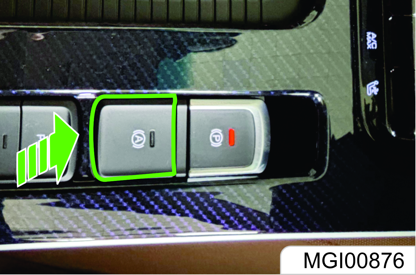
Automatic Vehicle Hold (AVH) Switch*
When the engine has been in operation, the driver’s safety belt is tightened, and the driver’s side door has been closed, you have to press the AVH switch, and the background lamp on the switch illuminates to activate the AVH function.
Afterwards, if following conditions are met, the AVH working indicator on the instrument illuminates. The parking brake will function and the brake system applies the braking force to park the vehicle in situ.
AVH Conditions (AVH Function Activated Firstly):
- The vehicle is motionless and the engine is running.
- The brake pedal is depressed to a degree (brake hydraulic pressure > 4 bar).
- The driver’s seat belt is buckled and the driver’s side door is closed.
Other Conditions (They Shall be Satisfied Simultaneously):
- No fault exists on the system.
- EPB has been released.
- The accelerator pedal has not been depressed (opening < 2%).
How to Manually Release Automatic Parking Brake After AVH?
Confirm that the ignition switch is at the ON position, depress the brake pedal, and press the EPB switch. The AVH working indicator goes out and the automatic parking brake is released.
Automatic Release After AVH
You do not have to manually press the EPB switch to release when starting the vehicle next time after AVH. Automatic release will be done when the system detects that you are going to start the vehicle.
Operate the engine, engage gear (drive gear or reverse gear), and the driver’s safety belt is tightened and the driver’s side door has been closed. Depress the accelerator and release the clutch. After the vehicle start conditions are met, the parking brake will be released automatically.
1.8 Opening & Closing
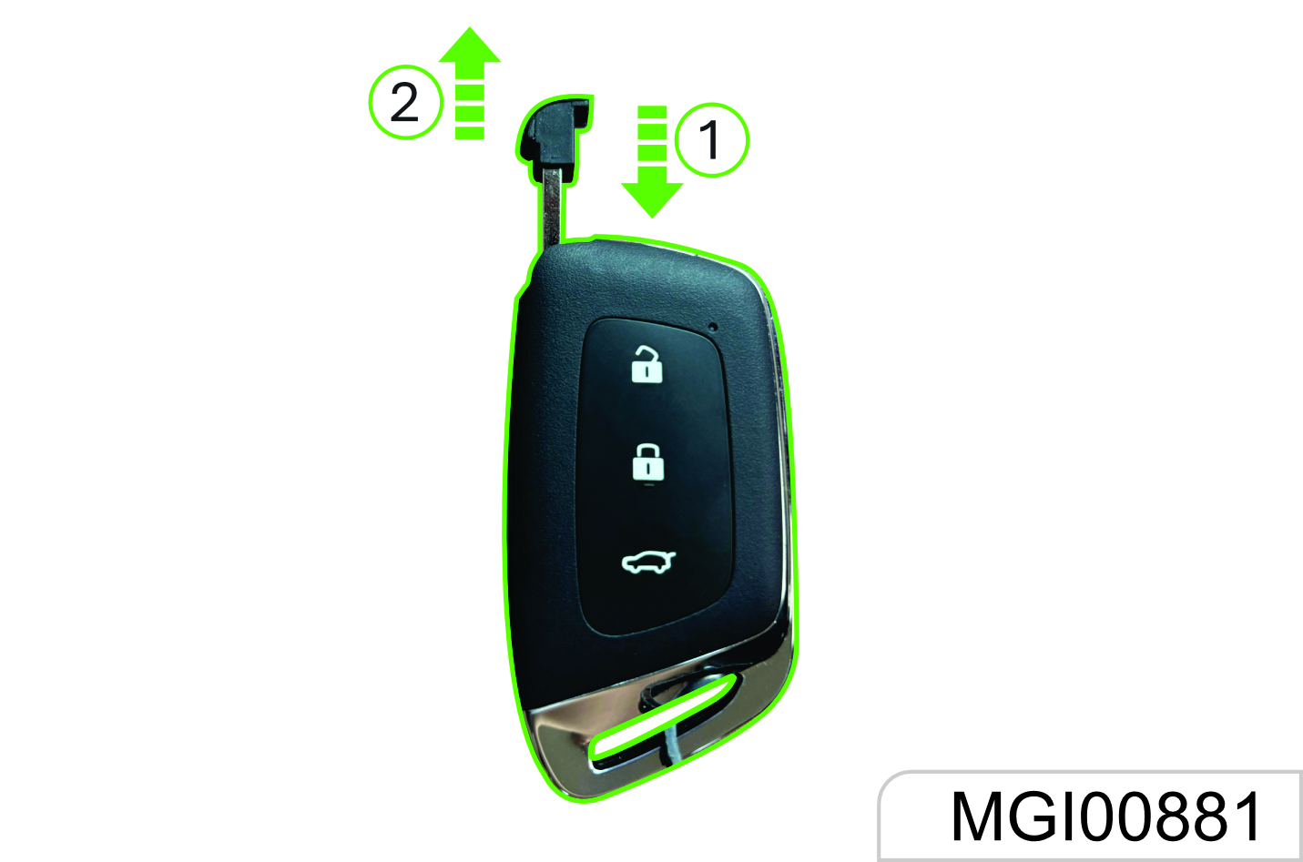
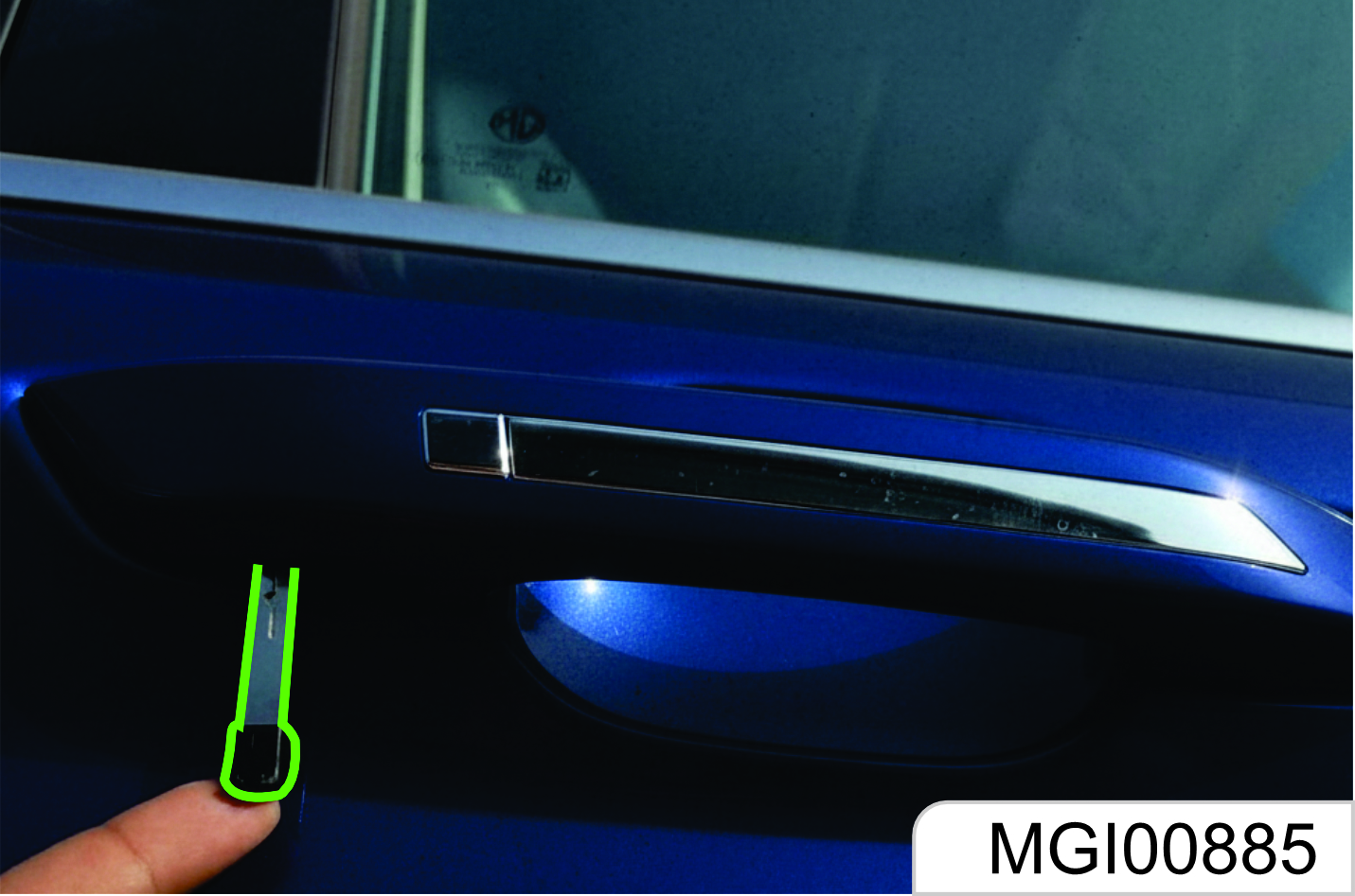
Type 1 Key
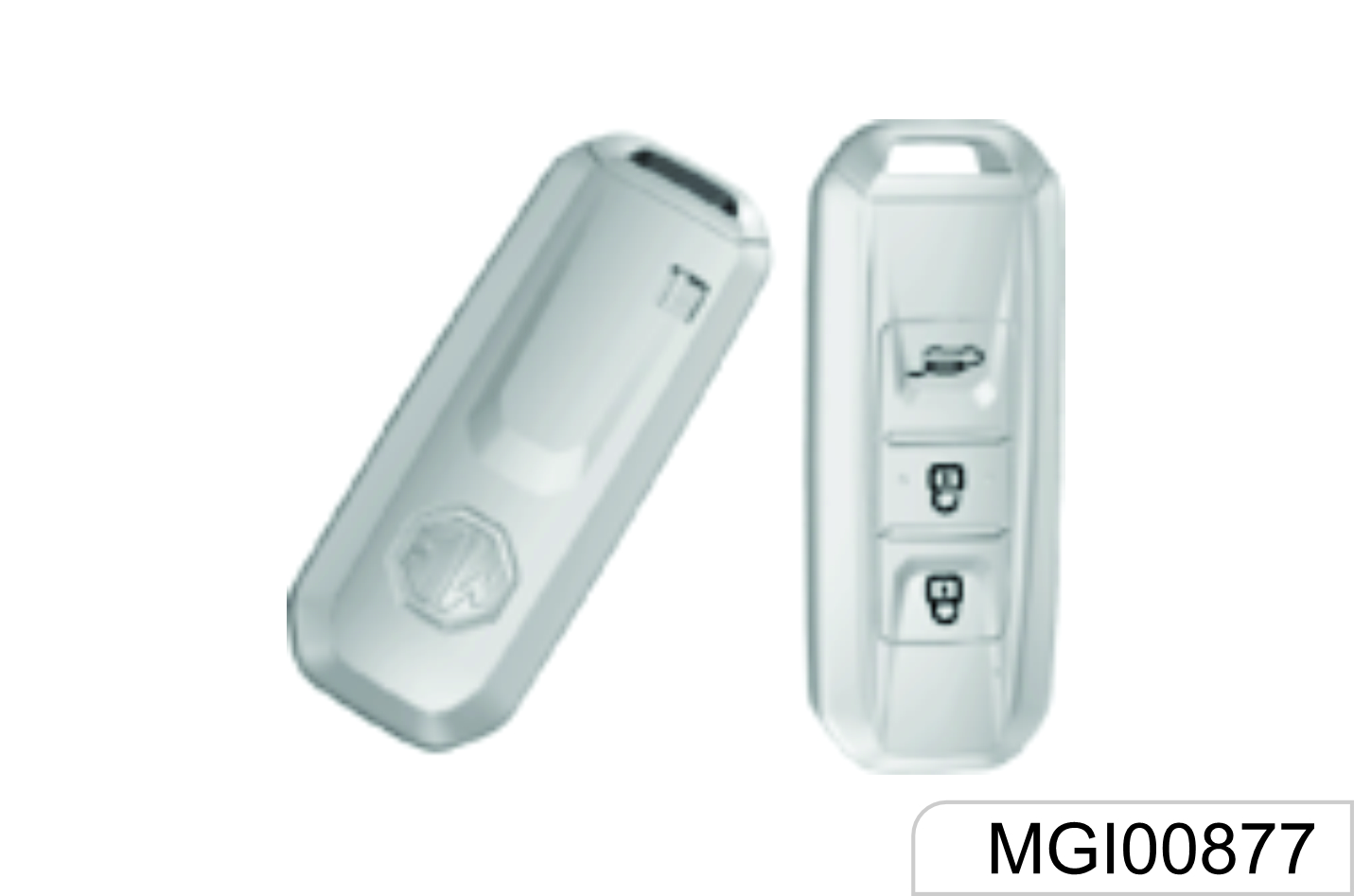
Detachable Type 1 Key
As shown in the figure above, turn the release switch
- on the key first and then pull out the mechanical key.
- Plug back the mechanical key after use.
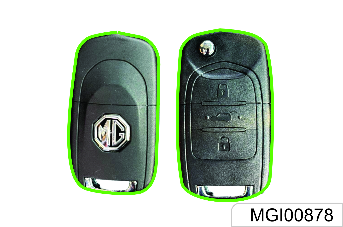
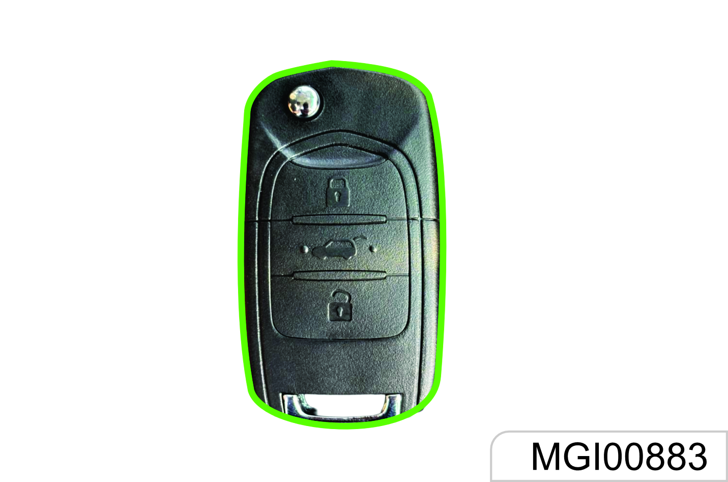
Type 2 Key
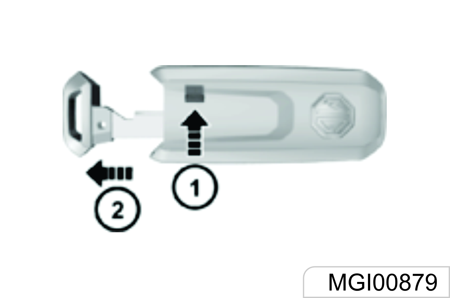
Type 3
Detachable Type 3 Key
As shown in the figure above, turn the release switch
- On the key first and then pull out the mechanical key.
- Plug back the mechanical key after use.
Each new vehicle is provided with two keys. Please reserve one key as spare.
For the sake of safety, please keep the key number plate in a safe place to prevent from illegal key making.
Different models may be provided with different keys. Please refer to real key.
Do not leave the key in the vehicle. Take the key with you when you leave the vehicle.
If the key is lost, please contact to JSW MG Authorised Service Centre.
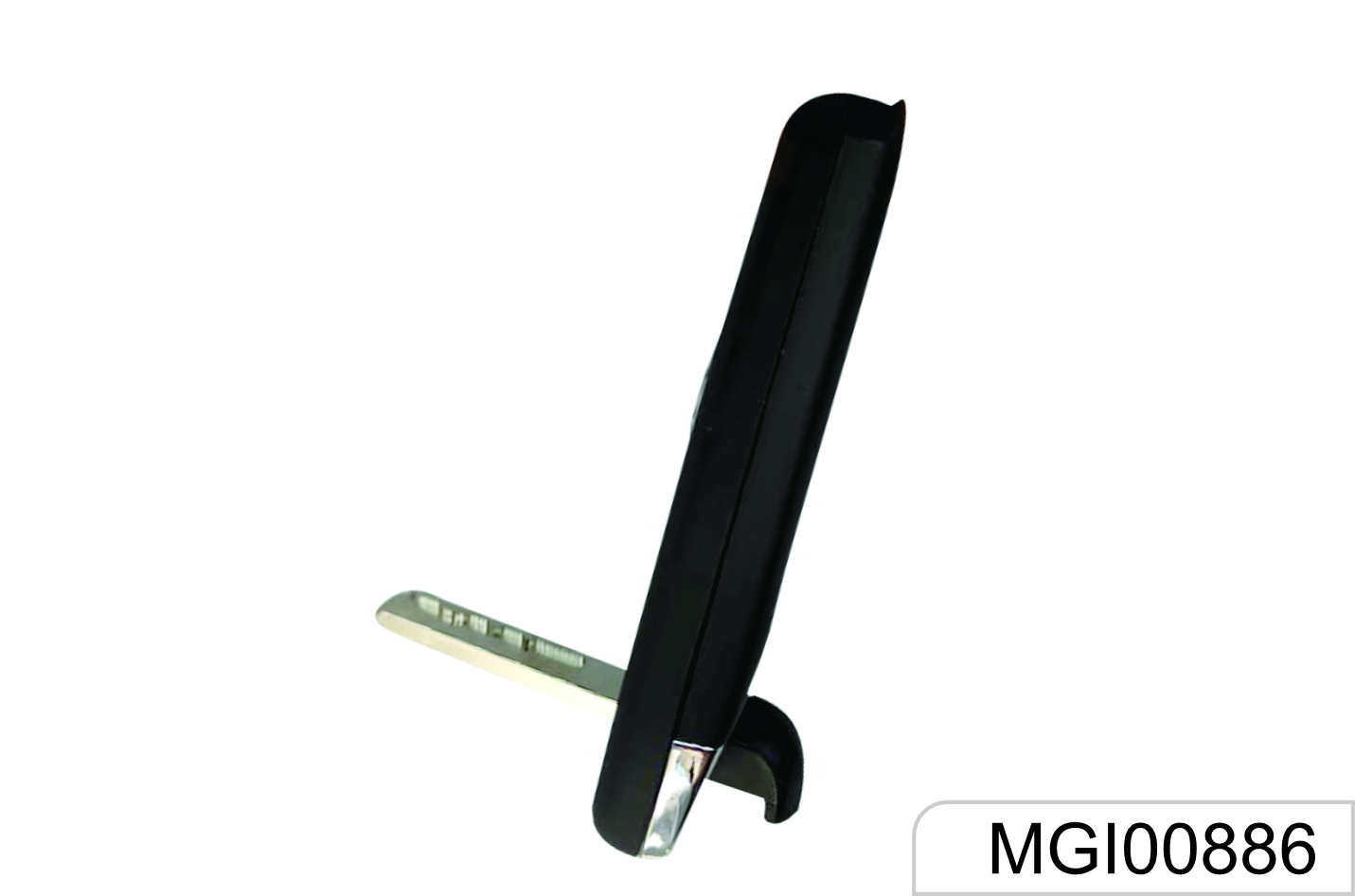
Foldable Type
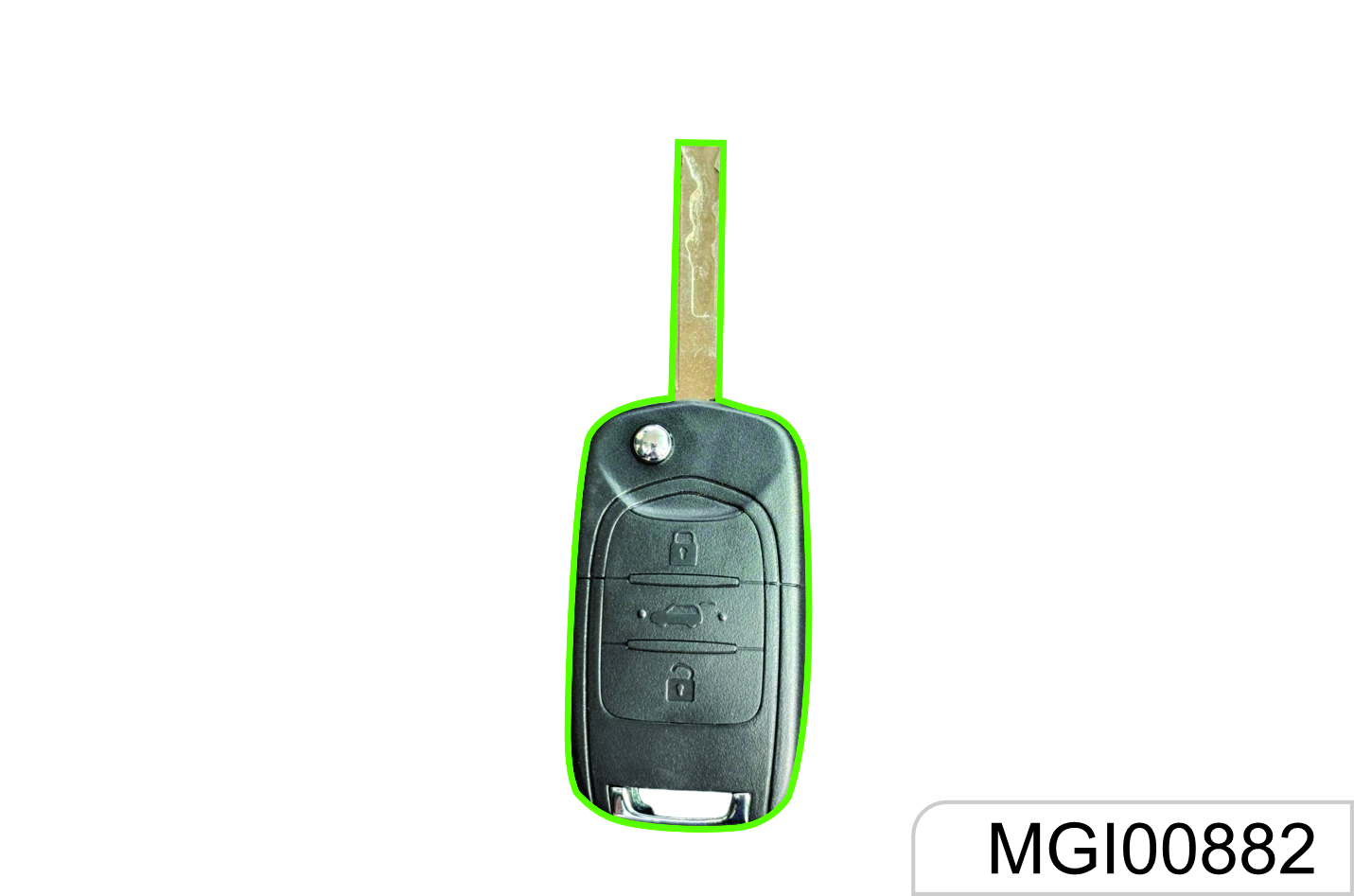
As shown in the figure, press the release button, and the mechanical key will pop up automatically.
Fold the mechanical key after use.
Key-in Reminder*
If the driver’s door is opened when the ignition key is at LOCK position and is not pulled out, the instrument will ring for prompt. The function reminds you to take the key with you when you leave the vehicle.
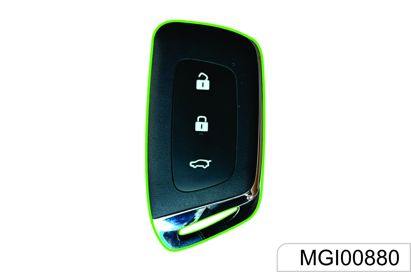
Remote Control
The effective distance of remote control is about 15m without shielding. When the ignition key is plugged in the switch or the ENGINE START STOP Switch is at ACC or ON position, the remote control does not function.
 Remote Lock Button. Press the
button once to lock all doors after
all doors are closed; the hazard
warning lamp will flash twice, and the
vehicle is at anti-theft state.
Remote Lock Button. Press the
button once to lock all doors after
all doors are closed; the hazard
warning lamp will flash twice, and the
vehicle is at anti-theft state.
 Remote Unlock Button. Press the
button once to unlock all doors; the
hazard warning lamp will flash once;
Anti-theft state is released.
Remote Unlock Button. Press the
button once to unlock all doors; the
hazard warning lamp will flash once;
Anti-theft state is released.
 Liftgate Unlock Button. Press and
hold for about 2s; open the liftgate, and
the hazard warning lamp will flash once.
Liftgate Unlock Button. Press and
hold for about 2s; open the liftgate, and
the hazard warning lamp will flash once.
The functioning range of the remote control may be different due to environmental reasons. Radio interference signals and barriers will affect the remote-control functions.
Smart key precaution*
The smart key functionality may be altered, or it may cause malfunction under following conditions:
the frequency band from the smart key may be mixed with a different frequency (from engine operation, door lock function, electronic systems, woofer, mobile phones, portable wired/ wireless charger, heating device, electronic power banks, e-cigarettes, etc.)
- If the smart key is near your mobile phone, its signal may be blocked by the normal operation of the phone.
- Do not place your smart key and mobile phone in the same pocket of jackets/pants.
- Do not place smart key over the wireless charger of the vehicle.
Vehicle Locating
Press the remote unlock button quickly for two times to activate the vehicle locating function, and the hazard warning lamp will flash 20 times.
Remote Window Lowering
Press and hold the unlock button for about 2s to lower all windows automatically and in turn.
Remote Opening of Panoramic Sunroof*
If the vehicle is configured with a panoramic sunroof, press the unlock button of the remote control for about 2s, the sun blind and sunroof will be opened automatically.
Activation of Door Lock and Anti-theft Mode
- Close all the windows.
- Turn the ignition key to LOCK position and pull out the key (if mechanical ignition key is configured).
- All passengers leave the vehicle.
- Close all doors and the engine hood.
Press and release the remote lock button. All doors are locked. The hazard warning lamp will flash twice, and the immobilizer is activated.
As for a vehicle configured with ENGINE START STOP function, only when the ignition switch is at LOCK position can the transmitter activates the immobilizer system.
The anti-theft mode must be activated with the transmitter.
- Warning sound
- Under the anti-theft state, when the unlock button on the transmitter is not pressed and any of the doors or liftgate is forced opened in an abnormal way (including use of a key), the system will make the hazard warning lamp flash and emit warning sound.
- To stop warning sound Press and hold the lock, unlock or liftgate button on the transmitter for about 2s or turn the key to ON position to stop the warning sound; if not, the warning sound will be ended automatically after 30s, and the anti-theft mode is activated again. If the system fails to do so, it is recommended to have the system checked by the JSW MG Authorised Service Centre.
Door Unlock and Release of Anti-theft Mode
-
Press the unlock button on the
remote control once.+
- All doors are unlocked.
- The hazard warning lamp flashes once.
- The anti-theft state is released.
-
Press and hold the liftgate open
button for 2s.
- The liftgate is opened.
- The hazard warning lamp flashes once.
- The anti-theft state is released.
Lock Function Alarm
The horn will buzz thrice and the hazard warning lamp will flash thrice to indicate that the doors are not locked
successfully if the remote lock button is pressed or passive locking is conducted when the door lock conditions are not met. These situations include:
- There is a door not closed (including liftgate)
- The door lock is under thermal protection
- The ignition switch is not at the LOCK position
- The passive entry system (if configured) detects a legal key in the vehicle.
Never leave a child or pet unattended in the vehicle. Otherwise, it may cause injuries or death due to high temperature in the vehicle.
Automatic Locking of Door
When all doors are closed and the vehicle speed exceeds 10 km/h, all doors will be locked automatically.
Automatic Re-locking
With the key not in the ignition switch, the vehicle will activate re-locking if the alarm is disarmed but any of the doors and liftgate is not opened within 30s after the vehicle is under the armed state successfully.
Ignition Off Unlocking
When the doors are locked, they will be unlocked automatically if the ignition switch is turned from ON position to ACC or LOCK position.
Remote Control
Each remote control has its own electronic code to prevent the doors being opened with other remote controls.
If the remote control is lost or stolen, please contact the JSW MG Authorized Service Center to buy a new one as soon as possible. If you need to replace one or more remote controls, please bring with you the existing remote control(s) when you go to the JSW MG Authorized Service Center. When the JSW MG Authorized Service Center matches the remote control for replacement with the vehicle, the existing remote control shall also be matched with the new code. After the new remote control is coded electronically, the lost remote control will not unlock your vehicle. For Type I key, 3 transmitters can be configured at most each time; for Type II and III keys, 4 transmitters can be configured at most each time.
Signal Transmission Autostop Function of Remote Control
The remote control has the signal transmission autostop function which can prevent unnecessary battery loss caused by misoperation and other reasons.
Long press any button on the remote control for over 10s, the remote control will stop transmitting signals automatically.
If the button is released, the signal transmission autostop function is deactivated.
Fault
If the remote control cannot function normally, it may be caused by the following reasons:
- Out of remote control working range;
- Excessively low remote control battery; Interference by external environment and other high-power radio signals (such as base station and launch tower);
- Signal blocking by other barriers.
Battery Replacement
Inside the key remote control, there is a lithium battery whose service life is 2 years generally. When the remote control distance is shortened gradually (i.e. must get closer to the vehicle), it indicates a low battery. The key battery cannot be charged. After the battery runs out, please go to the JSW MG Authorised Service Center to have the battery changed. Battery model: Cr2032.
To ensure normal functioning of the remote control, please follow the following rules:
- Avoid dropping the remote control.
- Please do not place a heavy object on the remote control.
- Make sure the remote control is away from water or direct sunlight. If the remote control is socked, please wipe with soft cloth.
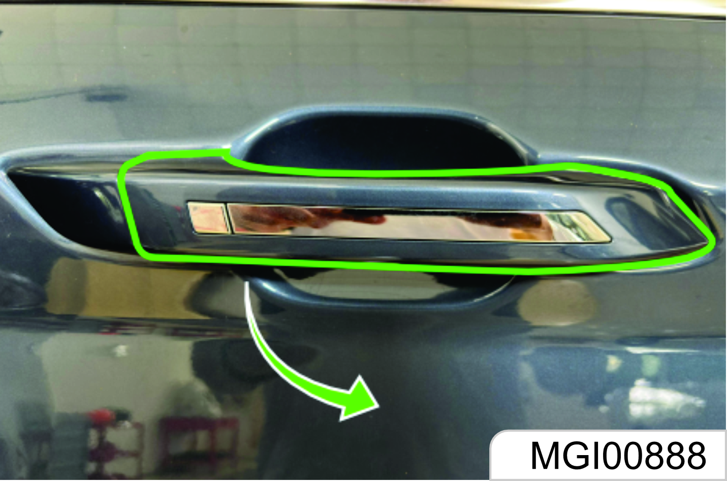
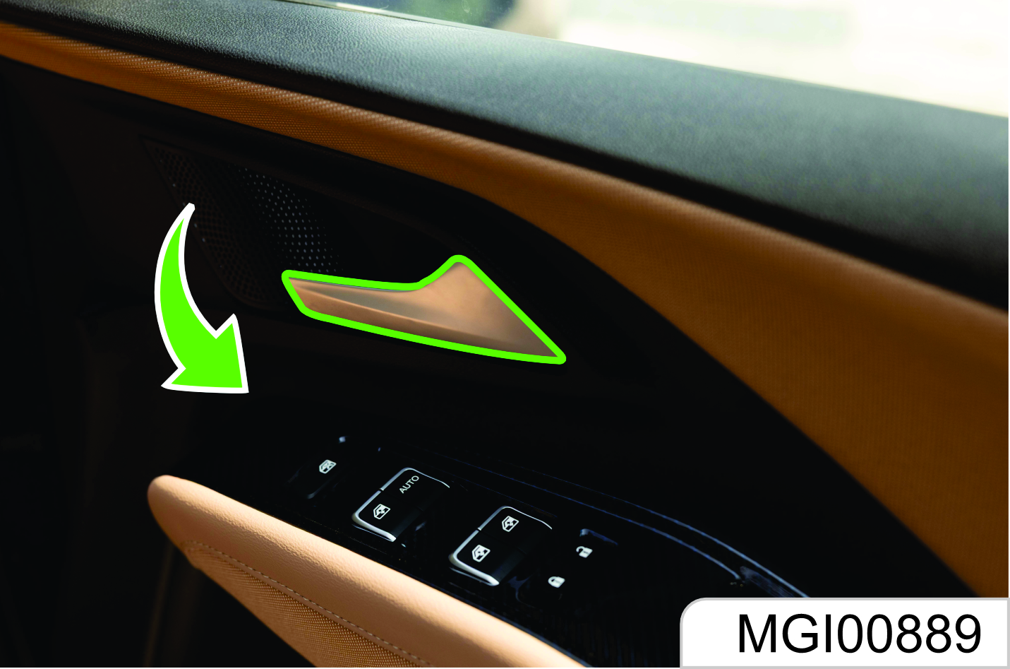
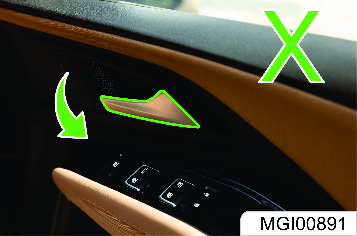
1.9 Door Lock
External Door Locking and Unlocking
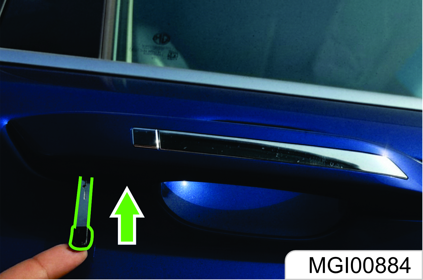
As shown in the figure above, the lock hole on the left front door external handle is hidden under the trim cover. The trim cover needs to be removed first if the key is used to open the door; for example, the remote control is lost or out of power.
Below the trim cover, there is a small hole.
Plug the key into the hole and press inward; at the same time, prize up the trim cover outward to remove the cover.
For installation, press the trim cover inward to fasten it.
To lock a door outside of the vehicle with a key, plug the key and rotate it clockwise.
Rotate the key counterclockwise to unlock the door.
Do not leave a child or pet alone in the vehicle. Otherwise, severe casualty will be caused. The child may operate power windows or other control buttons or even drive the vehicle. Do not leave the child with a key in the vehicle. Such behaviors may cause severe casualties.
As shown in the figure, for type III, when the door is locked or unlocked with a key from outside the vehicle, the key piece is first passed through the hole of the key to rotate the key piece.
When you leave the vehicle unattended, you must lock all doors and liftgate and take the key with you. If the doors and liftgate are unlocked, the vehicle may be stolen. Please park your vehicle in an attended place. It is recommended not to leave valuables in the vehicle to prevent losses due to unforeseen circumstances.
Internal Door Locking and Unlocking
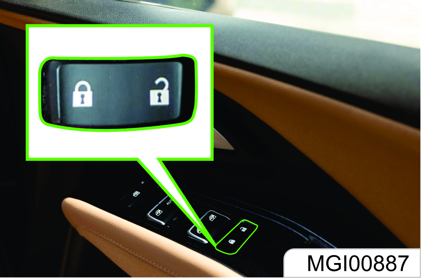
As shown in the figure, a central door lock switch is set on the middle of the instrument panel. To lock doors from inside, press the lock button on the central door lock switch. To unlock doors from inside, press the unlock button on the central door lock switch. If the lock button indicator is on, it means the doors are locked; if the indicator is off, it means the doors are unlocked.
External / Internal Door opening
To open doors from inside or outside, unlock the doors first, and pull the external or internal door handles.
When the doors are locked, pulling the internal door handle twice can open the doors.
A child shall sit on the rear seat, and the door shall be locked with the child safety lock.
Door Locking Method in Case of Vehicle Outage
In case of vehicle outage (for example, the battery is out of power, or its positive and negative poles are disconnected), the central door lock system does not function, and you need to lock side doors manually one by one. As shown in the figure above, open the right front door and two rear doors, and find the internal knobs of locks (not the knob of child safety lock).
Rotate the knobs outward with a key and close the doors. At last, pull the external handles to ensure that the doors are locked. At this time, please pull the internal handle once first if you want to open the door.
For the left front door, please plug the key in the external door handle and rotate the key clockwise to lock the door. Please refer to the content in the Subsection "External Door Locking and Unlocking".
If there is noise while opening/ closing doors or driving, apply lubricating grease on the door latches and hinges.
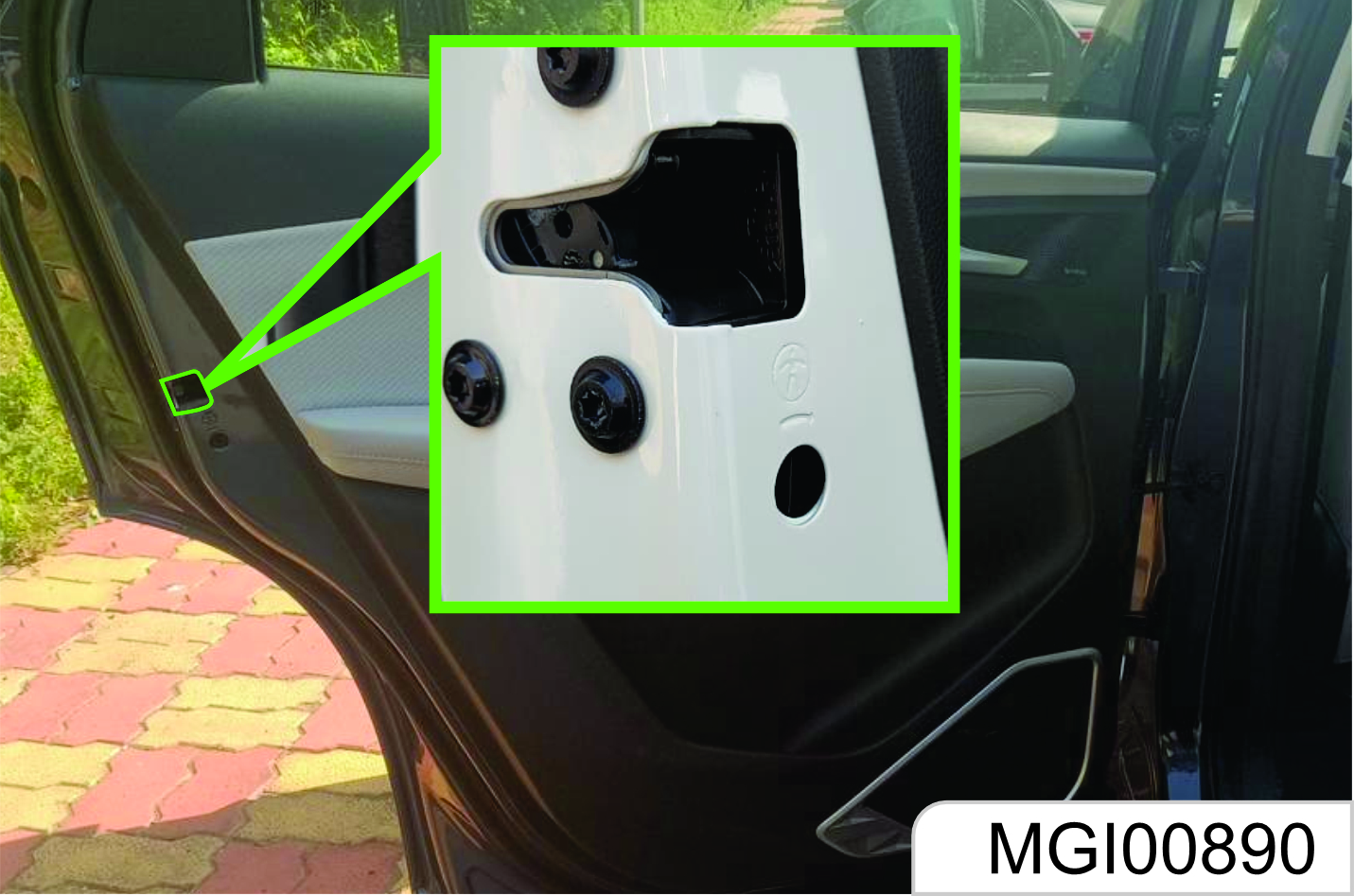
Child Safety Lock
The rear doors are equipped with child safety locks.
The function of the child safety lock is to prevent passengers (especially children) from pulling the door handle to open the rear door.
To activate the child safety lock:
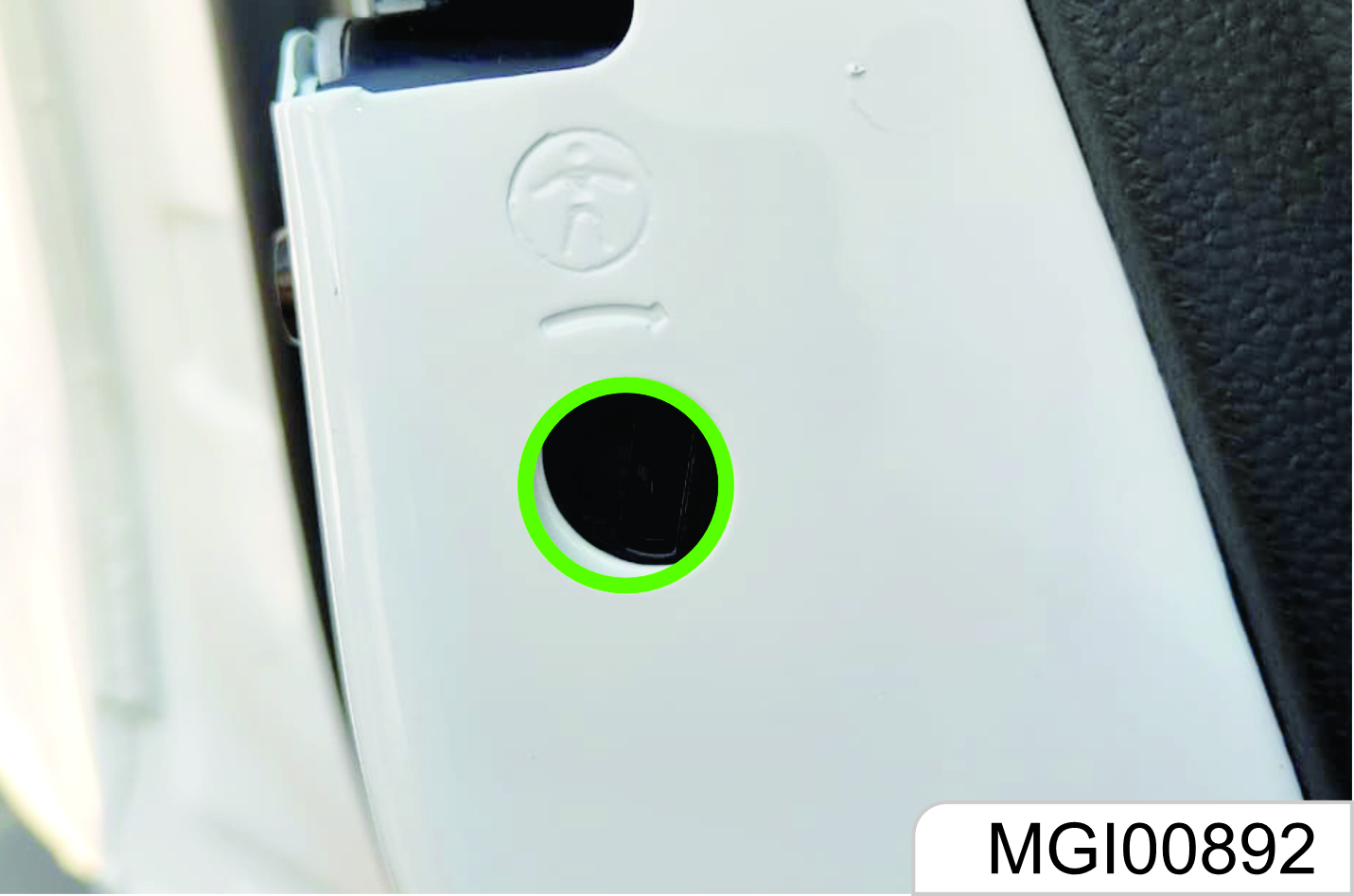
- Open the rear door that you want to lock.
- Find the child safety lock hole on the door edge and near the middle position.
- Plug the key and rotate as per the arrow to the lock position.
When the child safety lock is activated, you need to pull the external door handle to open the door. To deactivate the child safety lock, please plug the key and rotate to the unlock position.
The two rear doors are equipped with a child safety lock respectively. They function separately and must be activated manually and respectively.
When the child safety lock is activated, do not attempt to pull the internal door handle to open the door. otherwise, the door handle may be damaged.
Central Door Lock System
The central door lock system enables you to lock and unlock all doors with the remote control or the central door lock switch from inside.
Door Lock Thermal Protection
If the doors are unlocked / locked for over 10 times within 8s, the locks will be prohibited for 10s to protect them.
1.10 Doors
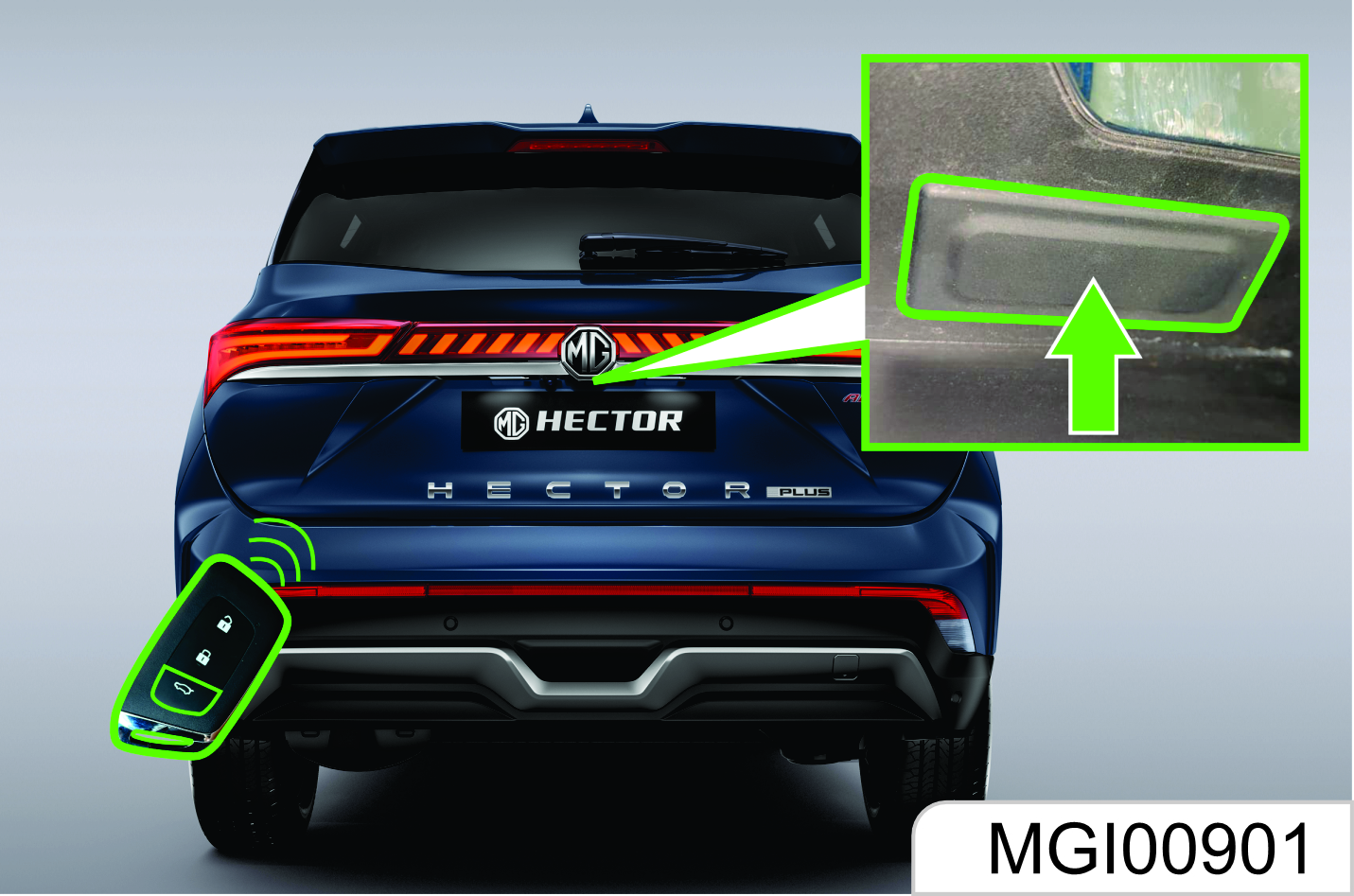
Liftgate.
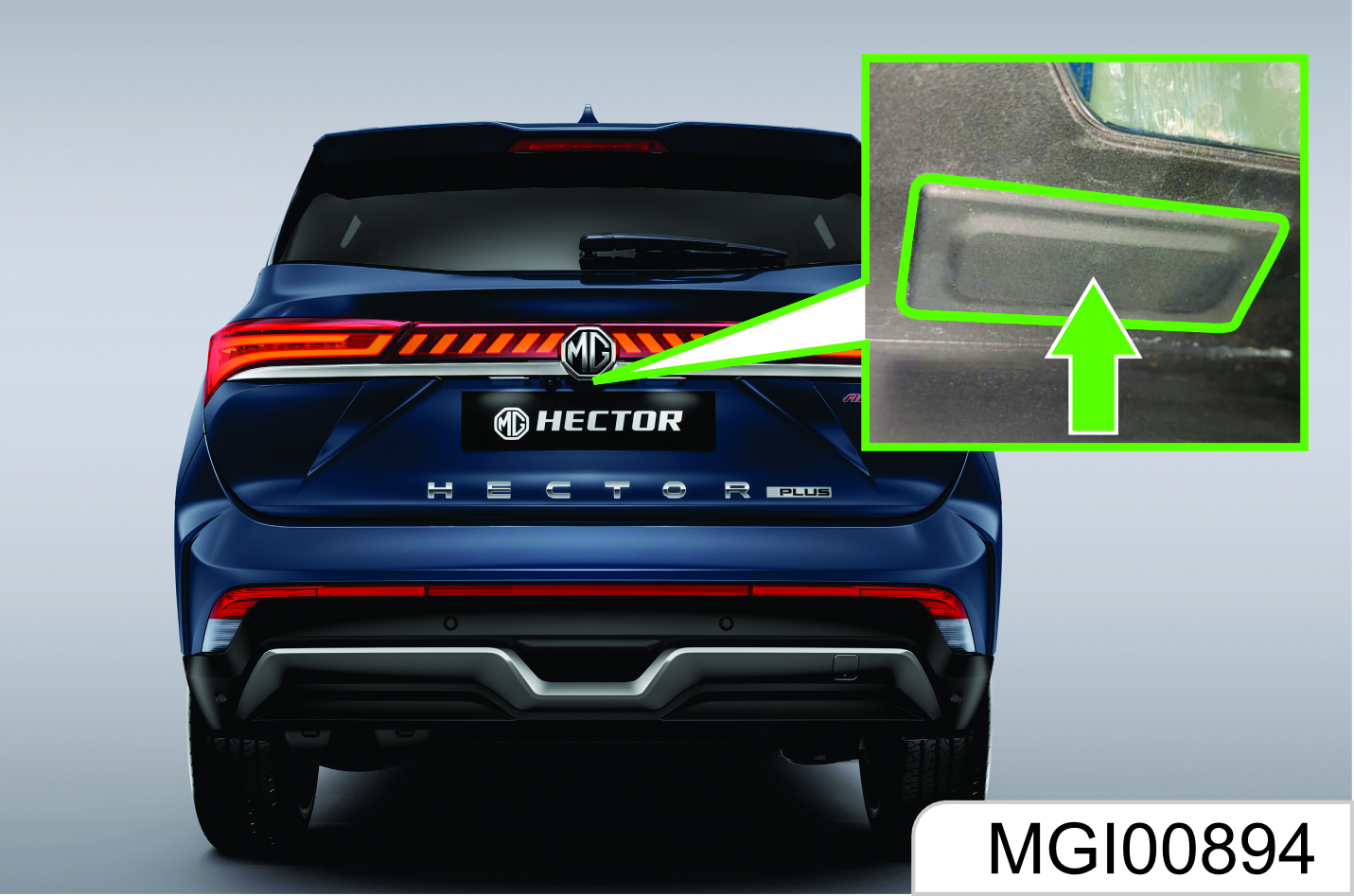
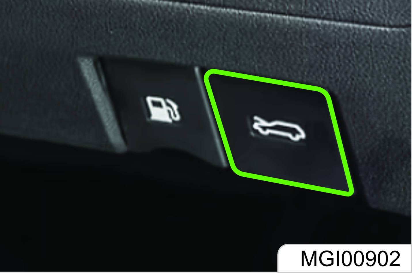
External Liftgate Switch

As shown in the figure, the liftgate release switch is above the liftgate license plate.
When the liftgate is to be opened, firstly, unlock the door, and then press the switch to unlock the liftgate, and open the liftgate.
According to the vehicle configuration, for the vehicles equipped with PEPS, you can directly carry the remote key to approach the liftgate and press the switch to open the liftgate when the vehicle is locked.
Liftgate Opening with Remote Key
Press the remote key liftgate opening key for about 3s to unlock the liftgate when the engine is shut down.
To lock the liftgate, you need to close it and then lock it.
Electric Liftgate*
Before opening the liftgate, make sure that the vehicle stops, the gear is in parking gear, and the handbrake is pulled to avoid any damage.
For AT model, you can operate the liftgate in Gear P.
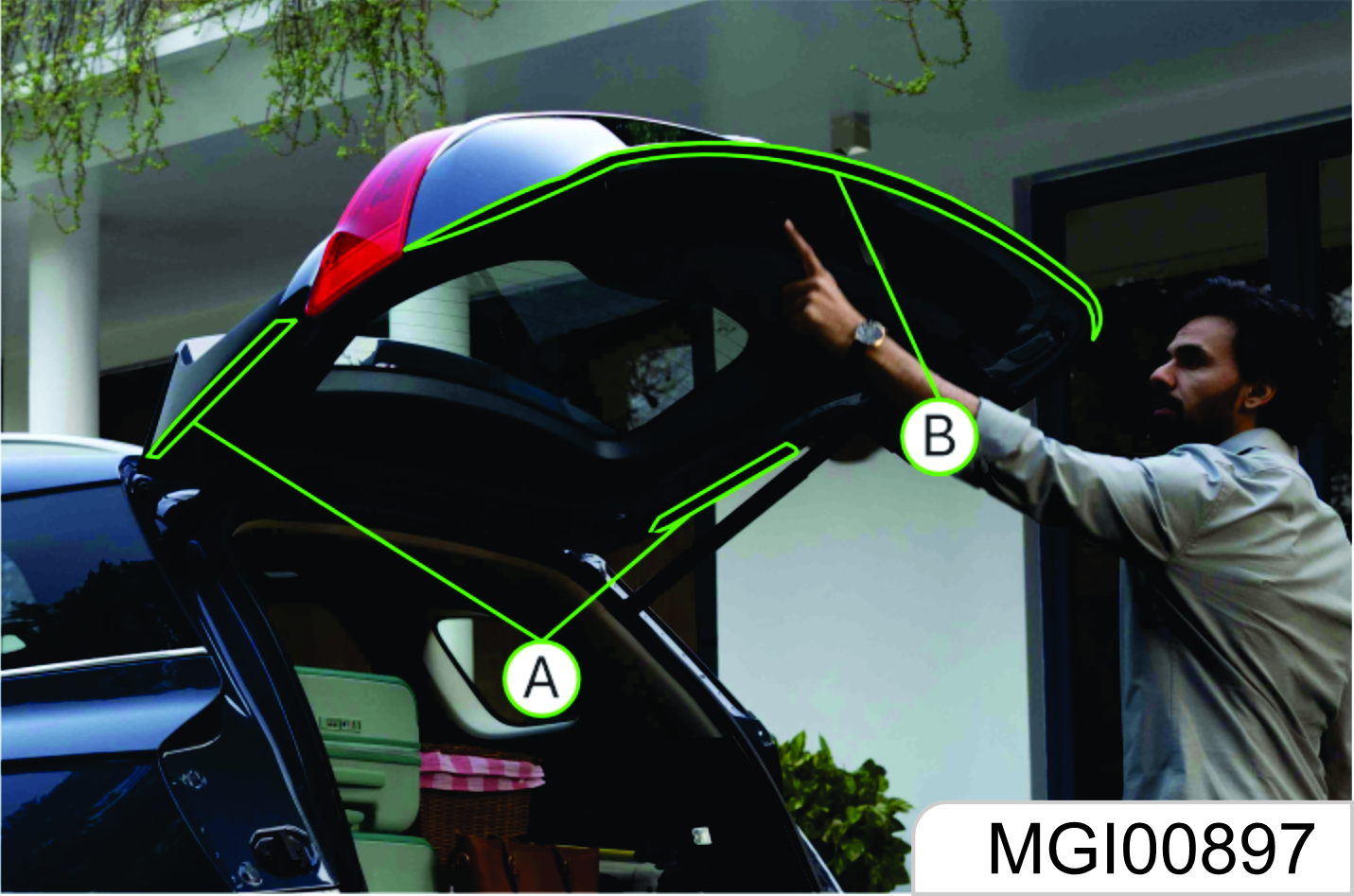
Make sure that your and other persons’ bodies are out of the opening range of the liftgate, your or other persons’ hands and other body parts are out of the closing range of the liftgate to avoid any personal injury during liftgate opening or closing.
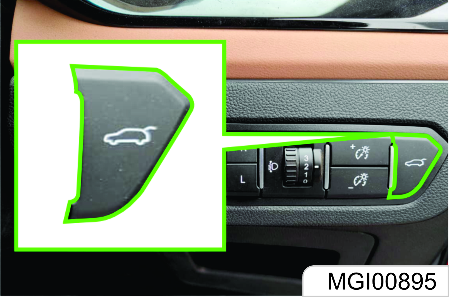
External Liftgate Switch
Firstly, unlock the vehicle, and press the switch. The liftgate automatically opens after two prompt tones. When the liftgate is to be closed, press the switch. The liftgate automatically closes after two prompt tones. The locking sound and two flashes of hazard warning lamp represent that the liftgate is closed and locked.
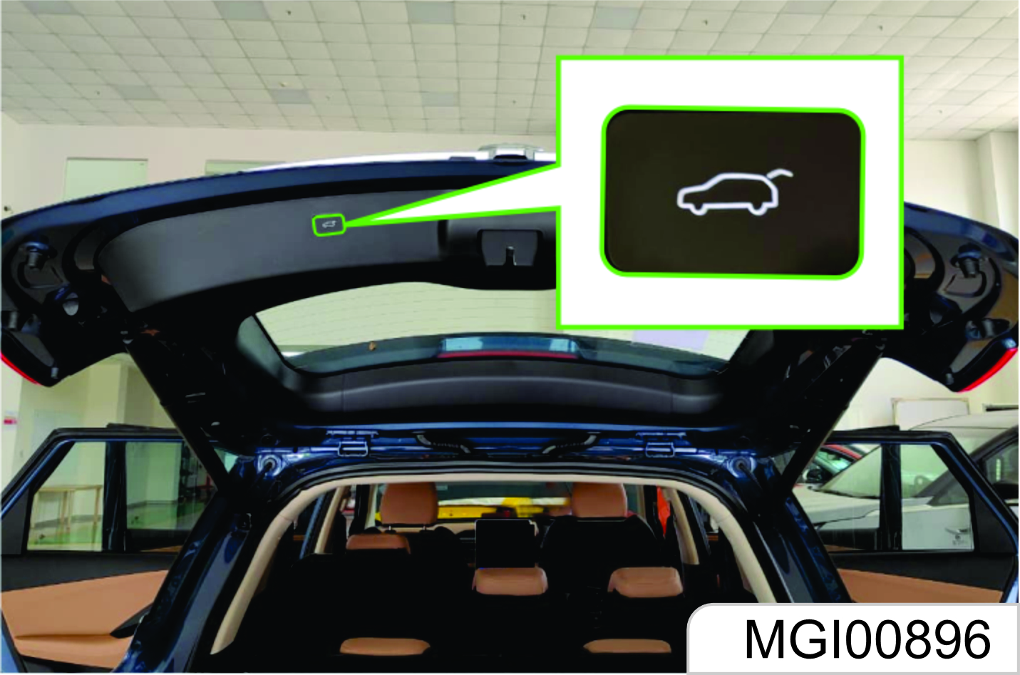
Internal Liftgate Switch
Press the switch. The liftgate automatically opens after two prompt tones. When the liftgate is to be closed, press the switch. The liftgate automatically closes after two prompt tones. The locking sound and two flashes of hazard warning lamp represent that the liftgate is closed and locked.
Before driving, please make sure that the liftgate is closed and locked. When leaving the vehicle, make sure that the liftgate is closed and locked, and the vehicle is locked.
Liftgate Closing Switch
In the liftgate open state, press the liftgate closing switch, as shown in the figure. The liftgate automatically closes after two prompt tones. The locking sound and two flashes of hazard warning lamp represent that the liftgate is closed and locked.
During liftgate opening or closing, press this switch shortly. The liftgate will stop at the present position.
Setting of liftgate opening height: Adjust the opening height slowly manually after the liftgate is open. Press this switch for 3s after adjustment, and hear a prompt tone to end the setting. The subsequent liftgate opens to this height to stop.
You can also pull the liftgate to close with hands. When a certain speed is reached, the liftgate will enter the electric closing mode.
Anti-pinch Function of Liftgate
Firstly, unlock the vehicle, and press the switch. The liftgate automatically opens after two prompt tones. When the liftgate is to be closed, press the switch. The liftgate automatically closes after two prompt tones. The locking sound and two flashes of hazard warning lamp represent that the liftgate is closed and locked.
For the anti-pinch function of the liftgate, a better anti-pinch cannot be realized at every position. The position closer to the liftgate hinge has a stronger anti-pinch force. Please keep your finger or other body parts away from the range of movement to avoid any personal injury.
Liftgate Antiplay
Before the liftgate is not completely locked, if the anti-pinch strip is triggered 3 times, then the liftgate enters antiplay mode. The liftgate stops moving, and the switch is invalid. Please close the liftgate manually.
Inductive Tailgate
The inductive tailgate can be opened without touching the vehicle.
How to use the Inductive Tailgate
The tailgate can be opened with notouch activation satisfying all the conditions below.
- The power supply of the vehicle is in the Of
- The speed is less than 2km/h or the vehicle’s gearbox is in P gear
- Driver side and Tail Gate Door locked
- The legal key is near the tailgate
Automatic Opening
The hazard warning lights will beep 2 times and flash 1 time and tailgate will slowly open.
Automatic Closing
If the tailgate is closed, there will be 2 beeps. After all the doors are locked, there will be 2 double flashes.
Power Lift Gate Relearning Procedure After Factory Reset
In the event of a factory reset from Infotainment System, the power lift gate shall be operated either by IP switch or by Key Fob for the first time.
Detect and Alert
The Tailgate operates if the smart key is detected within 50 ~ 100 cm from the tailgate. The alert stops at once if the smart key is positioned outside the detecting area during the Detect and Alert to customer. If you are positioned in the detecting area 50 ~100 cm behind the vehicle carrying the vehicle key, the hazard warning lights will blink for about 3 seconds to alert you the smart key has been detected and the tailgate will open.
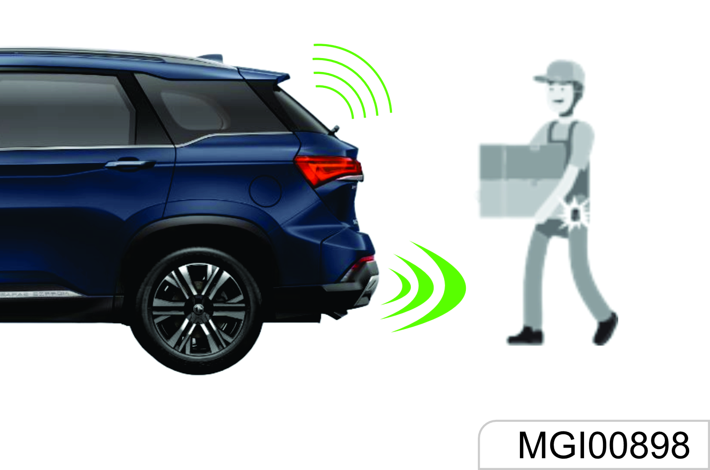
Do not approach the detecting area if you do not want the tailgate to open. If you have unintentionally entered the detecting area and the hazard warning lights and beep starts, leave the detecting area after checking the tailgate is in closed condition.
Liftgate Service Hole
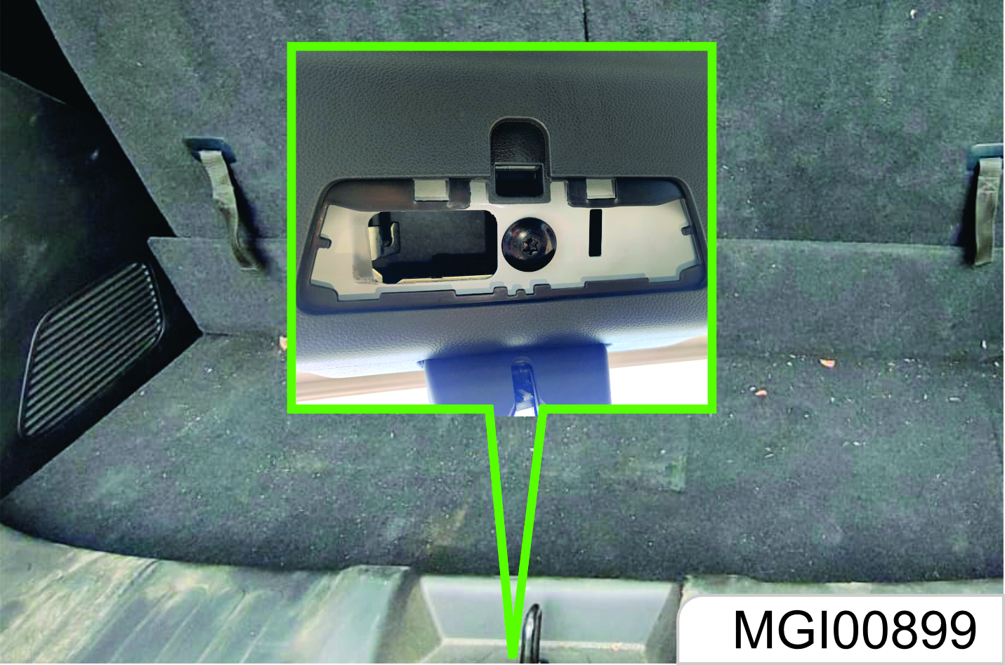
If other liftgate opening methods are invalid, the liftgate can be opened for service as per the following steps:
- Fold the rear seat backrests, and get to the trunk.
- Open the trim cover outside the liftgate lock, as shown in the figure above.
- Insert a very small straight screwdriver into the rightmost end of the slot and move the lever in the slot leftward. The liftgate is opened when an unlock sound is heard.
If the operation is correct, but the liftgate cannot be opened and closed normally with qualified conditions to open and close the electric liftgate, it is recommended to drive to the nearest Aftersales Service Center for repair.
Passive Entry Passive Start (PEPS) System*
High-configured models are equipped with PEPS system. You can lock or unlock the doors conveniently only by taking the remote-control key with you and getting to the certain ranges of the front doors or lift gate. You can lock or unlock remotely without taking your key out from your pocket.
Passive Entry
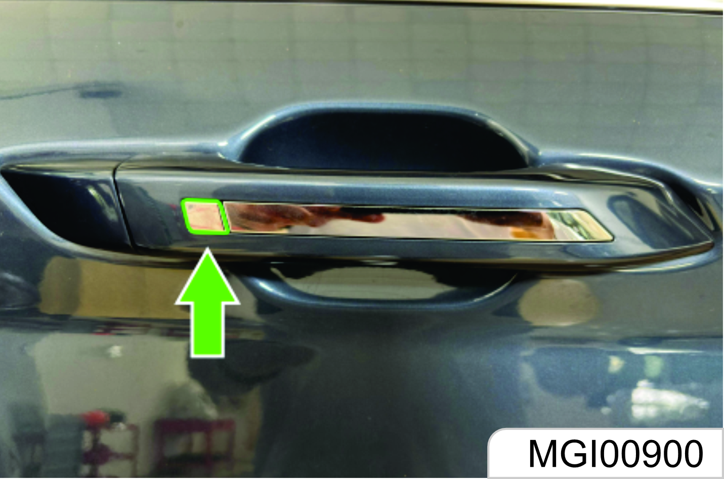
When the doors are locked and the ignition switch is at LOCK position, bring a legal key and get close to the front door handle (within 1.2 m); press the button on the handle, and the system will certify the key. Once certified successfully, the system will unlock all doors. The hazard warning lamp flashes once.
Passive Locking
When all doors are closed and the ignition switch is at LOCK position, bring a legal key and get close to the front door handle (within 1.2 m); press the button on the handle, and the system will certify with the key. Once certified successfully, the system will lock all doors. The hazard warning lamp flashes twice.
The system will send warning prompt, the horn will buzz thrice, and the hazard warning lamp will flash thrice to indicate that the doors are not locked when you press the button on the door handle in case of the following situations:
- There is a door not closed.
- The ignition switch is not at LOCK position.
- There is a key in the vehicle. Check one by one and then lock again.
When opening the liftgate, make sure that all body parts are not within the opening range after hearing a prompt tone of opening, to avoid any personal injury during liftgate opening.
1.11 Passive Unlocking / Locking of Liftgate
Passive Unlocking
When the doors are locked and the ignition switch is at LOCK position, bring a legal key and get close to the liftgate (within 1.2 m);
press the liftgate release switch, and the system will certify with the key. Once certified successfully, the system will unlock the liftgate, and the liftgate pops open.
If the doors are already unlocked, the liftgate can be opened by pressing the liftgate release switch directly (unnecessary to bring the key and get close to the liftgate).
Passive Locking
If the doors are locked, when the lift gate is closed, the system will search automatically whether there is a legal key in the vehicle. If there is no legal key in the vehicle, the lift gate will be locked automatically
The hazard warning lamp flashes twice. If there is a key in the vehicle, the system will send warning prompt, the horn will buzz thrice, and the hazard warning lamp will flash thrice; the four side doors will be unlocked automatically.
Please take away the key in the vehicle and lock the doors again.
If the doors are unlocked, the lift gate can only be locked after closing the liftgate and locking the doors. Please remember to lock the doors.
Before driving, please make sure that the liftgate is closed and locked.
If the remote control battery is low, the passive entry / locking function may fail, and you can use the mechanical key to lock / unlock doors. Please replace the remote control battery as soon as possible.
1.12 Engine Hood
Opening Engine Hood
- Pull the engine hood release handle on the left lower side of the instrument panel.
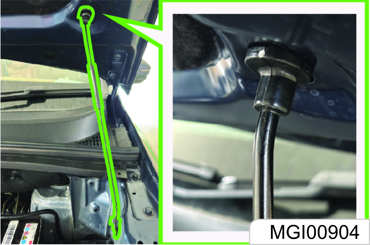
- After the engine hood is opened slightly, stretch out the hand to the lower side of the engine hood front edge. Pull the engine hood release handle upward as shown in the figure to open the engine hood completely.

- Separate the engine hood prop rod from the fixing clamp. Plug the free end of the prop rod in the slot.
Closing Engine Hood
- Support the engine hood to prevent it from closing and take the prop rod out from the slot. Then, fix the rod in the fixing clamp.
- Make sure that your or other persons’ hands or other body parts are away from the engine compartment, engine hood and vehicle body edges.
- Slowly drop the engine hood and release it when the engine hood front edge is about 30 cm vertically from the top cross member of the water tank to let it fall freely.
- Always check and confirm that the engine hood is locked in place.
- Pull the engine hood front edge before driving to make sure that the engine hood is locked.
- Do not pull the engine hood release handle when the vehicle is moving.
- Do not drive the vehicle when the engine hood is open. If the engine hood is open, the drivers sight will be blocked.
Driving when the engine hood is open may cause a collision accident, damaging your vehicle or other properties or leading to casualties.
Starting & Driving
2.1 Driving Instructions
Vehicle Control
Do not slide if the engine is out of operation.
In such case, many systems (such as brake booster) cannot function. Driving in this way will cause a danger to yourself and others.
Pedal
To ensure that the pedal travel is unhampered, the floor mat in the pedal area shall not be excessively thick, and no article shall be placed in the pedal area.
Emergency Measures
One Tyre is Punctured when the Vehicle is Running
The operation time of the starter motor shall not exceed 10s once. otherwise, the starter motor will get damaged or discharge of battery will occur.
If one tyre is punctured when the vehicle is running, the driver shall hold the steering wheel tightly to control the driving direction, slowly decelerate, turn on the hazard flasher, and gently depress the brake pedal to park your vehicle in a safe area.
Do not brake suddenly when one tyre is punctured. Braking suddenly will cause the vehicle to tilt towards one side, and thus an accident may be caused.
One Fault exists when the Vehicle is Running
If one fault exists when the vehicle is running, the driver shall turn on the hazard flasher, slowly decelerate, and park the vehicle in a safe area at the curb.
Place a warning triangle at a position 50 m behind the vehicle in the daytime while placing it at a position 100 m behind the vehicle at night. Please follow requirements of traffic laws and regulations.
After inspection, send the vehicle to the JSW MG Authorised Service Center for inspection and maintenance.
Place the warning triangle in the trunk, or have the customer give it to you when the vehicle is being delivered.
If the Engine Does Not Work
In case the ignition switch is at the START position, if the starter motor does not work, please check whether the battery is dead, whether the battery port is connected correctly and whether relevant fuses get damaged.
If the starter motor works but the engine fails to be started, please check fuel level, fuel filter, fuel pump, relevant wiring, etc. The operation condition of the fuel pump can be preliminarily judged by hearing sounds made by the ignition switch when it is being turned on.
Measures Taken in Case of Engine Overheat
When the vehicle is running, if the output power of the engine reduces suddenly or the warning lamp on the instrument indicates excessively high temperature illuminates, park your vehicle in a safe area and take the following measures:
- Have the engine run at idle and turn the transmission at the neutral position.
- Pull the parking brake lever.
- Turn off the A/C.
- Open the bonnet to ventilate the engine bay.
- If the level of the coolant reservoir does not drop, stop the engine to cool it.
If the coolant level is very low, uncover the reservoir, slowly fill water in the reservoir drop by drop till the level reaches the MAX (maximum) level mark of the coolant reservoir.
- After taking provisional measures, immediately send the vehicle to the JSW MG Authorised Service Centre for inspection.
Do not open the bonnet if steam or coolant overflows from engine parts. Otherwise, you may be scalded by steam or coolant.
Suddenly filling cold water in the overheated engine will damage the engine. The handling method above is taken in case of an emergency. When the engine gets overheated, you are suggested to contact the JSW MG Authorised Service Center for solution.
When the engine gets heated, uncovering the coolant reservoir will get steam or coolant overflowed, and thus your face or other body parts may be scalded.
If you are to uncover the coolant reservoir, you can do it after the engine cools down completely. Apply one cloth to the cover, open it slightly at first (by 1/3-1/2), and then open it fully after pressure in the reservoir is released completely.
Operation in Heavy Snow
- Decelerate when the vehicle turns at corner, upgrades or crosses a bridge.
- Please avoid parking on a hard road shoulder; otherwise, the snow shovelling work will be obstructed.
- Please keep safe distance from other vehicles; braking unnecessarily should be limited.
- Clear the accumulated snow around the vehicle frequently, for such measure can prevent the exhaust pipe from being blocked.
E-Call (Safety)*
Emergency Situation
In circumstances wherein the Vehicle has met with an Unpreventable accident, the safety feature of E-call shall trigger, wherein Emergency Assistance Services shall be provided to the driver of the Vehicle.
E-Call*

Any accident which causes the deployment of airbags, shall automatically trigger the feature of E-Call, in the concerned Vehicle, An automated call will be triggered from to your JSW MG Car from 24X7 JSW MG Team for ascertaining the well being of the Driver, and to take further steps to mitigate the damage, which may vary case to case.
*Instant help on Best Effort basis 24x7 through E-call icon Available in Head unit.
In below conditions E-call may not be received to customer.
- If harness / wiring / Auxiliary/HV/ lV Battery or any other technical or other interruption or obstruction.
- Areas with poor mobile Network coverage or no network connectivity.
Please note the same is a safety feature and may or may not be triggered in situations wherein the damage/accident has affected the functioning of the Vehicle concerned
To make Sure, your E-Call works:
- If you do not hear Emergency Assistance within 2 minutes of the crash, the system may be damaged or non-functional.
- It is advised to primarily make a call via one’s own mobile phone or using the i- call feature on the Head Unit, as the E- call reaching the Driver is dependent upon the intensity of the accident.
- This feature only works in countries or regions where Emergency Assistance can call the local emergency services. Visit the JSW MG Website for Details.
- For the feature to work the vehicle must have battery power, good network area along with other ancillary requirements to trigger the call.
- Always ensure your Primary number and alternate number is updated.
2.2 Start and Operation
Trial Run of New Vehicle
The following measures can be taken within the initial mileage of 500 km, which can improve the performance, promote the vehicle economy and extend the service life:
- Avoid starting the engine by depressing the accelerator fully.
- Do not keep the engine idling for a long time.
- Avoid any emergency shutdown except in an emergency. With this, the brake can run in well.
- Do not quickly start, accelerate suddenly and continuously keep the vehicle running at high speed if possible, to avoid any damage to the engine and save the fuel.
- Avoid accelerating by depressing the accelerator fully at a low gear and driving by depressing the accelerator greatly.
- Do not drag any other vehicle.
Please do not use such vehicle electric equipment as audio and head lamp for a long time under the condition that the engine is off. When leaving the vehicle, please also shut down the electric equipment for the vehicle, to avoid the battery from running out. If the battery runs out, the vehicle may fail to be started.
Mechanical Ignition Switch Position*
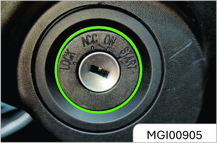
When the ignition switch is turned at the right side of the steering column, the operating positions are as follows: LOCK, ACC, ON and START.
LOCK
Lock the steering wheel. Remove the key and turn the steering wheel till the steering wheel is locked.
If you cannot turn the key when unlocking the steering wheel, you can gently turn the steering wheel to right/ left for one thing and turn the key for another.
ACC
The engine can be shut down when the ignition key is turned to the ACC position without the need to lock the steering wheel.
If you are to turn the ignition key from the ACC position to the LOCK position, you can gently press in the key and turn the key to the LOCK position. When the ignition key is at the ACC position, some electrical accessories such as radio and cigar lighter can be used.
ON
Connect the ignition system and electrical accessories.
Do not keep the key at "ON" for a long time when the engine is out of operation. Otherwise the battery will be discharged.
START
Start the engine. After starting the engine, release the key; the key will automatically return to the ON position.
Confirm that the engine does not operate before turning the ignition key to the START position.
Never remove the key or turn the key switch when the vehicle is running.
Otherwise, the brake assistance will disappear and the steering wheel may be locked. Therefore, the driver will lose control of the vehicle and thus the vehicle damage and the casualty accident may be caused.
Engine START STOP Switch Position*
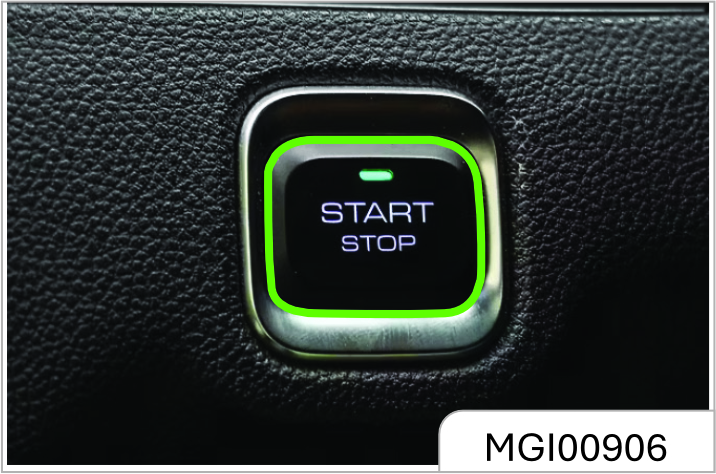
The ENGINE START STOP switch is at the lower right side of the instrument cluster.
Working indicator on ENGINE START STOP switch:
Orange: It indicates that the ignition switch is at the ACC or ON position.
Green: It indicates that the start conditions are met.
When the working indicator turns green, if the transmission is at the neutral or P position, press the start switch and then the engine can be started.
When the power is switched from the low voltage to the high voltage, the system must be able to detect the legal key. Please place the key at one position near the ENGINE START STOP switch inside the vehicle, such as the driver’s pocket or instrument panel storage box.
In the sequence from the low voltage to the high voltage of power, the operating positions are as follows: LOCK, ACC, ON and START.
LOCK
Parking is carried out at the position. The working indicator on the ENGINE START STOP switch does not illuminate, and the vehicle power is off.
ACC
Press the ENGINE START STOP switch at the LOCK position; the position can be switched to the ACC position. The orange working indicator on the ENGINE START STOP switch starts to illuminate. At the position, power supplies of some electrical accessories such as audio and cigar lighter are connected.
If no operation is conducted, the system will automatically return to the LOCK position 1h later, so as to reduce the consumed power.
ON
Driving and start are conducted at the position. Press the ENGINE START STOP switch at the ACC position once; the position can be switched to the ON position. The instrument cluster indicator illuminates, and the orange indicator on the ENGINE START STOP switch illuminates.
If you press the ENGINE START STOP switch once (without other operations) at the ON position, the switch will be turned to LOCK position.
START
At the ON position, turn the transmission at the neutral position, and depress the clutch pedal (for MT model) or brake pedal (for AT model). Then the green indicator on the ENGINE START STOP switch illuminates. Press the ENGINE START STOP switch once, and the engine will start. After the engine starts, the ignition switch keeps at the ON position.
OFF
Press the start switch once (vehicle speed < 2 Km/h).
Never keep the engine idling at high speed for over 5 min.
Excess temperature will damage the exhaust system.
For AT model, never release the brake pedal in the process of starting the engine; otherwise, the engine may fail to start.
If the transmission is not at the neutral or P position, the engine can not start.
Electronic Steering Column Lock*
As the electronic steering column lock is used to lock the steering wheel, the vehicle having the ENGINE START STOP function is equipped with the electronic steering column lock at the same time. You can hear the operating sound when the lock device is started or released.
If locking the steering wheel is required, following conditions shall be met at the same time:
- The vehicle is motionless.
- The ignition switch is at the LOCK position.
When conditions above are met, the steering wheel will be locked immediately if any one of following actions occur:
- Open or close the left front door.
- Remote locking.
- Wait 24s later.
If unlocking the steering wheel is required, you can just enter the vehicle with the legal key and press the ENGINE START STOP switch.
In case that the steering column lock may be unable to be released when it is in the wheel- deviation forward direction, the instrument cluster will display" Failure in locking of electronic steering lock" and buzz for prompt. At this time, align the steering wheel, turn the ignition switch at the ON position, and then switch to the LOCK position, to make efforts to unlock the steering wheel. If unlocking fails, check the vehicle.
Engine Starting
Before starting the engine:
- Ensure that no barriers exist around the vehicle.
- Ensure that all windows and doors are clean and transparent.
- Check whether the tyre conditions and the inflation pressure are proper and whether foreign matters exist.
- Adjust the seat headrest to a proper position.
- Adjust the rearview mirrors inside / outside the vehicle.
- Fasten the safety belt and ask all passengers to fasten safety belts.
- When turning the key at the ON position, check the operating conditions of the warning lamp and the indicator on the instrument panel.
- Regularly (e.g., when refuelling) check the maintenance items recorded in the Manual.
Engine Starting:
- Apply the parking brake.
- Ensure that seats and rearview mirrors are at proper positions. Adjust them if necessary.
- Turn the ignition switch at the ON position.
- Ensure that the gear lever is at the neutral or P position, and then depress the clutch pedal fully. Please depress the brake pedal for the AT model.
- Do not depress the accelerator pedal, turn the ignition-switch key to the ON position, and release the clutch (or brake) pedal after the engine starts. For one model having the ENGINE START STOP function, click the ENGINE START STOP switch once to start the engine. If the engine starts temporarily and fails to operate, you can wait for 10s and then try again.
- Keep the engine idling for more than 30s to heat the engine.
- Release the parking brake.
- Do not drive the vehicle at high speed before the engine temperature reaches the normal operating temperature.
Keep the engine idling for 3-5 min before the vehicle with the turbocharged engine starts to run, especially in winter or after storage for a long time, and after the engine oil is changed or the engine is maintained.
- Do not keep the starter running continuously for over 10s.
- It may be difficult to start the vehicle in extremely low temperature.
- It may be difficult to start the vehicle in one high-altitude area.
- If the engine fails to start, please wait for 10s and then restart so as to avoid any damage to the starter.
Turbocharged Engine Shutdown
After keeping the turbocharged engine operating at high speed for a long time, please firstly keep it idling for 3-5 min and then kill it, to cool the turbocharger. Otherwise, the turbocharger may get damaged due to overheating.
The turbocharged engine shall not idle for a long time. The idling time shall not exceed 20 min.
ENGINE START STOP Function*
Start Condition
Following conditions shall be met for engine start:
- The legal key is inside the vehicle;
- Depress the clutch pedal (for MT model) or brake pedal (for AT model).
If conditions above are met, the green indicator on the ENGINE START STOP switch will illuminate. In this case, if the gear is at the neutral or P position, press the start switch and the engine will immediately start.
Other Control Instructions
1. Emergency start
- The brake or clutch switch failure will make the start conditions unable to be met, and thus the engine cannot start in the normal procedures. You can firstly turn the ignition switch at the ACC position, confirm that the transmission is at the neutral or P position, and then long press the ENGINE START STOP switch for 15s. In this case, emergency start of the engine succeeds.
- Insufficient battery of the remote key may cause the system to fail to search for the key and thus the engine fails to start. In this case, you can firstly depress the clutch pedal (brake pedal for AT model), and at the same time attach the side of remote key close to the ENGINE START STOP switch. When the green indicator on the ENGINE START STOP switch illuminates, press the switch to start the engine. Please try again if you fail. You shall replace the battery of the remote key.
2. Emergency flameout
If emergency flameout of the engine is required when the vehicle is running, you can long press the ENGINE START STOP switch for 2s or continuously press for 3 times within 3s.
Never have a kid operate the ENGINE START STOP switch in any case; otherwise unexpected start or flameout of the vehicle, and the vehicle damage and the casualty accident may be caused.
Never operate the ENGINE START STOP switch when the vehicle is running. Accidental vehicle flameout may suspend braking and assistance of the steering system. In this case, the driver will lose control of the vehicle and thus the vehicle damage and the casualty accident may be caused.
Cruise Control System *
Type-1 Switch
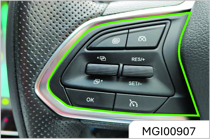
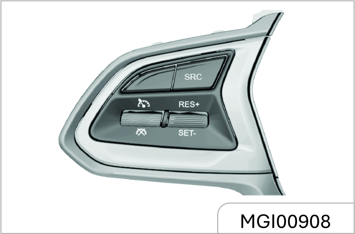
As the switch of cruise control system is at the steering wheel, when the cruise control system is started, the vehicle can run at such speed. Depress the brake pedal, and the function will be immediately disabled. Except that the brake pedal is used to disable the function, operating switches such as parking brake switch and clutch switch can also be used to disable the function of the cruise control system. The system can be used at 3, 4, 5 and 6 gears with a speed range of 40 Km/h - 120 Km/h when the engine speed is lower than 4800 rpm. For the AT model, the minimum speed for starting the cruise control system is 48 Km/h. Specific application method:
First Step: Cruise Start
Based on the cruise control system
switch type, press the "
 " button
or pull the toggle button towards
"
" button
or pull the toggle button towards
"
 " direction, and then the cruise
indicator on the instrument cluster
starts flickering, indicating that the
cruise control system enters the
activated state; pull the middle button
" direction, and then the cruise
indicator on the instrument cluster
starts flickering, indicating that the
cruise control system enters the
activated state; pull the middle button
towards the "SET/-" direction, and the
cruise start succeeds and the cruise
indicator of instrument is normally
on. (For example, when the driver
intends to stabilize the speed at 100
km/h, the driver must first speed up
to 100 km/h. When the speed reaches
100 km/h, he/she shall press the
"
 " toggle button and then pull the
toggle button towards the" SET/-"
direction. At this time, release the
accelerator pedal, and the vehicle will
continuously run at the speed of 100
km/h). After setting the cruising speed,
you can also use the accelerator pedal
to accelerate in the normal method;
after the accelerator pedal is released,
the system will recover the speed to the
original cruising speed.
" toggle button and then pull the
toggle button towards the" SET/-"
direction. At this time, release the
accelerator pedal, and the vehicle will
continuously run at the speed of 100
km/h). After setting the cruising speed,
you can also use the accelerator pedal
to accelerate in the normal method;
after the accelerator pedal is released,
the system will recover the speed to the
original cruising speed.
Second Step: How to Deactivate Cruise
If you are to immediately decelerate
in case of any emergency in front
during cruise control, you can depress
the brake pedal or clutch pedal or
press the cruise deactivation button
"
 " or pull the toggle button towards
"
" or pull the toggle button towards
"
 " direction. In this case, the vehicle
exits from the current cruise state
and enters the cruise activation state,
and the cruise indicator of instrument
flickers; if you press the "
" direction. In this case, the vehicle
exits from the current cruise state
and enters the cruise activation state,
and the cruise indicator of instrument
flickers; if you press the "
 " button
in the cruise state, the whole cruise
system will be deactivated, and the
instrument indicator will go out.
" button
in the cruise state, the whole cruise
system will be deactivated, and the
instrument indicator will go out.
Third Step: Operation for Cruise Recovery
When the vehicle exits from the cruise state and enters the cruise activation state, if you are to carry out the cruise control at the previous cruising speed, you just need pull the toggle button once towards the "RES/+" direction. Then cruise control is carried out at the previously-saved speed recovered. For example, the cruising speed is 60 Km/h before braking and becomes 50 Km/h after braking, and at the time the cruise indicator of instrument flickers. Pull the toggle button once towards the "RES/+" direction; the cruise indicator will be normally on, and the vehicle will automatically speed up to 60 Km/h and enter the cruise control state.
Fourth Step: How to Promote Cruise Control Speed
Pull the toggle button towards the "RES/+" direction and the set cruising speed will rise without the need to depress the accelerator pedal. The speed will rise by 2 km/h every time you pull up the switch once. If the toggle button is kept pressed, the vehicle speed will continuously rise. Once the switch is released, the then running speed will be saved into the memory and the vehicle will cruise at the speed.
Fifth Step: How to Reduce Cruise Control Speed
Pull the toggle button towards the "SET/-" direction to reduce the cruising speed. The speed will reduce by 2 km/h every time you pull down the switch once. If the toggle button is kept pressed, the vehicle speed will continuously reduce. Once the control lever is released, the then running speed will be saved into the memory and the vehicle will cruise at the speed. If the toggle button is released when the vehicle speed reduces to about 40 km/h (less than 40 km/h), the saved value will be deleted. If you are to continuously drive at the cruise control speed, you need reset the cruising speed.
In principle, the cruise control system can be used on one expressway or one totally-closed road. It is not allowed to use the cruise control system in rainy, icy and snowy weather, and on one densely- hillside road or denselycrooked road. Cruise control is also not proper on a rugged pavement and when too many vehicles run on one road.
For the MT model, after the cruise control system is started, if you intend to shift the transmission to the neutral position, always depress the clutch pedal firstly. Otherwise, it may cause the engine to overspeed and thus get damaged.
Engine Immobilizer System
The vehicle with the engine immobilizer system has the extra anti-theft capacity, for the system can prevent any unauthorized person from starting the vehicle. The matching key of the engine immobilizer system has been encoded electronically. The electronic transceiver is concealed in the ignition key. Only a valid key can be used to start the engine. However, an invalid key can also be used to open doors. The engine immobilizer system isolates the power supply from the ignition system, the fuel pump and the fuel injector. When any unauthorized person turns the invalid key to the START position, the engine immobilizer system fails to identify the electronic code. Therefore, the engine cannot start and the immobilizer system indicator will be flickering.
If the vehicle is equipped with one steering wheel mechanical lock again, a better anti-theft result will be realized.
Parking
- When the parking brake is used for parking, the button shall be released after parking. When parking on a ramp, tension the parking brake as tightly as possible and depress the brake pedal at the same time.
- Shut down the engine and turn off the ignition switch. Turn the steering wheel till the steering wheel is locked by the steering wheel lock.
- When parking the vehicle on one uphill ramp, turn the front wheels away from the road shoulder. When parking the vehicle on one downhill ramp, turn the front wheels towards the road shoulder.
- When parking the vehicle on one downhill ramp, turn the front wheels towards the road shoulder.
Do not park and drive the vehicle on inflammables such as straw and hay. If such inflammables cannot be avoided, park the vehicle to check and confirm that these inflammables are not attached at the chassis after the vehicle passes the inflammables.
Otherwise, these inflammables may be ignited by high-temperature compon- ents on the chassis, and thus a fire accident is caused.
2.3 Manual Transmission*
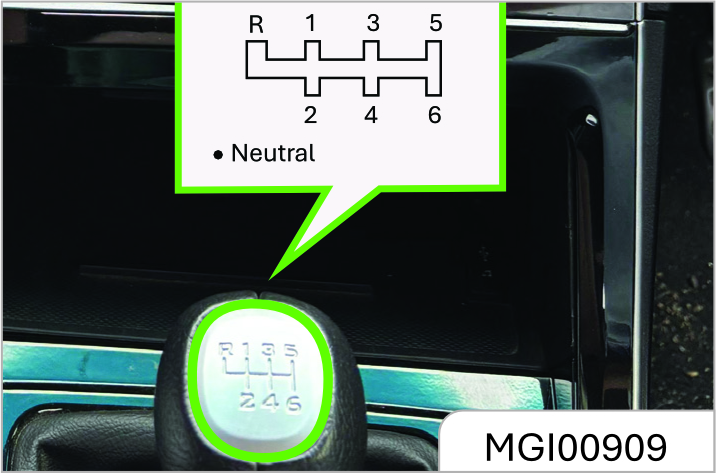
Shift the gear as per gear positions marked on the gear lever ball after the clutch is released. If you have to shift to the reverse gear, you must first stop the vehicle, depress the clutch, and shift the gear lever from the neutral (N) gear to the reverse (R) gear.
1: First drive gear
2: Second drive gear
3: Third drive gear
4: Fourth drive gear
5: Fifth drive gear
6: Sixth drive gear
R: Reverse gear
Depress the clutch pedal completely when shifting gear. Do not always put your foot on the clutch pedal during driving.
Operation for Shifting Transmission with Six Drive Gears to Reverse (R) Gear
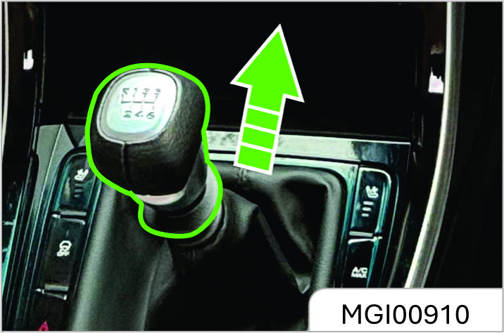
As shown in the figure above, when shifting the transmission with 6-speed Gearbox to the reverse (R) gear, pull up the reverse gear lock ring firstly and then turn the gear lever from the neutral (N) gear to the reverse (R) gear. Take care not to pull the reverse gear lock ring when shifting to the drive gear, so as to avoid from shifting to the reverse gear accidentally.
When shifting between the drive gear and the reverse gear, be sure to ensure that the vehicle comes to a complete stop. After completely depressing the clutch, wait for a moment and engage a gear.
Otherwise, the transmission may get damaged or the transmission service life may be shortened.
When reversing your vehicle, please slowly start and confirm that the vehicle is shifted to the reverse (R) gear, for engaging a wrong gear may cause an accident.
Always putting your foot on the clutch pedal during driving will damage the engine and the clutch system and increase the consumed fuel volume.
Do not slide your vehicle at the neutral gear; otherwise, the transmission will get seriously damaged or an accident will be caused.
2.4 Automatic Continuously Variable Transmission (CVT)
*
Your vehicle may be equipped with one automatic Continuously Variable Transmission, which is a wet automatic Continuously Variable Transmission with 6 gears.
Instruction for Use
- Before starting the engine, depress the brake pedal firstly to confirm that the transmission gear lever is at the P gear, and then the engine can be started.
- Depress the brake pedal and then engage gear after you start the engine.
- Continuously depress the brake pedal after you engage gear, release the electronic parking brake, and release the brake pedal after you are ready to start the vehicle.
- After the brake pedal is released on a smooth pavement, the vehicle will start running automatically and slowly with the accelerator pedal not depressed.
- Sliding your vehicle at the neutral gear is prohibited during driving; otherwise, the transmission will get seriously damaged or an accident will be caused.
Shifting
Locking Button
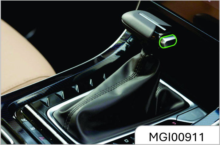
Only one locking button exists on the gear lever, and this button is used to avoid the driver from selecting the parking (P) gear or reverse (R) gear when the vehicle runs at other gears.
Do not press the button while the vehicle is running.
It is required to press the button only when the vehicle comes to a complete stop and you intends to engage the parking (P) gear or reverse (R) gear.
Gear Lever Operation
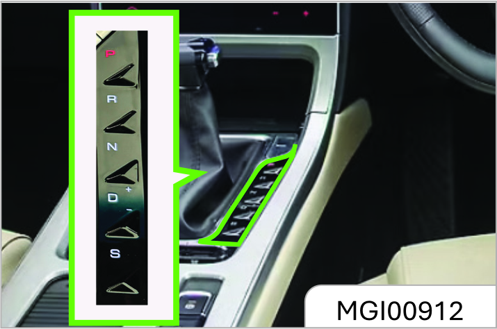
Operate the gear lever as indicated by arrows below when shifting gear.
- Shift gear freely
- Press and hold the locking button to shift gear.
- Press and hold the locking button and at the same time depress the brake pedal to shift gear.
The requirements for operations to switch the neutral (N) gear to the drive (D) gear are relevant to the vehicle speed and the duration of the gear lever at the neutral(N) gear. In some cases, you have to depress the brake pedal and then the neutral (N) gear can be switched to the drive (D) gear. For example, the duration of the gear lever at the neutral (N) gear is over 2s when the vehicle is 5 km/h.
Gear
P: Parking Gear
The transmission is locked mechanically at the parking gear. Engage the parking (P) gear when the vehicle is motionless and the hand brake is drawn back.
When you park your vehicle on a ramp, you should first depress the brake pedal and draw back the hand brake and then engage the parking (P) gear.
R: Reverse gear
The reverse (R) gear can be engaged only when the vehicle is motionless, and the engine idles.
N: Neutral Gear
The neutral (N) gear can be engaged when the vehicle is motionless, and the engine idles for a long time (for such purposes as waiting for a traffic light or for a traffic jam).
D: Drive Gear (Economy Mode)
It is used for normal driving. The transmission automatically selects among 6 drive gears according to the vehicle speed and the accelerator pedal position.
The economy mode among the automatic modes is selected at the gear. The optimum fuel consumption and discharge can be provided in the economy mode.
S: Drive Gear (Sport Mode)Turn the gear lever from the (D) position right to the (S) position. The sport mode among the automatic modes is selected at the gear. Better operating performance can be provided in the sport mode. You can also switch to the manual mode at the gear.
+/-: Upshift / Downshift in Manual Mode
If you are to toggle the gear lever from the (S) position to the (+) or (-) position once, select the manual mode.
After selecting the manual mode, toggle the gear lever to the (+) position once, and one gear will be increased. If the vehicle speed is excessively low, the system will not implement the upshift command and the instrument will ring for prompt. It is recommended to upshift manually when the engine speed is 1600~2000 rpm.
Toggle the gear lever to the (-) position, and one gear will be reduced. If the vehicle speed is excessively high, the system will not implement the downshift command, and the instrument will ring for prompt.
If the gear lever is toggled from the (S) position to the (D) position, the vehicle is switched to the automatic gearshift mode.
When the vehicle runs in the manual mode, if the engine speed is lower than one constant value, the transmission will automatically downshift to the adjacent low gear, so as to avoid the engine flameout from occurring. When the vehicle speeds up, and the engine speed continuously rises and reaches to the maximum speed allowed within gears, the transmission will automatically upshift to the adjacent high gear, so as to protect the engine.
Switching the gear lever from the drive (D) gear to the reverse (R) gear or parking (P) gear is prohibited during driving; otherwise, the transmission will get seriously damaged or an accident will be caused. Only when the vehicle comes to a complete stop can the reverse (R) gear or parking (P) gear be engaged.
Gear Display
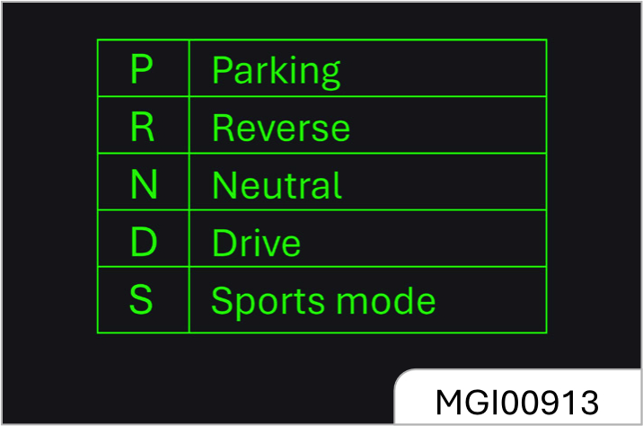
The gear information is shown on the instrument cluster display.
Upshifting Reminding
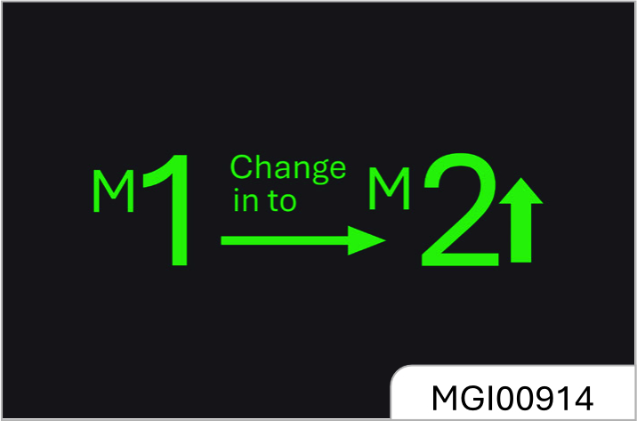
As shown in the figure above, when the vehicle is running in the manual mode, if the vehicle speed is excessively high at the current gear, the instrument will ring for upshift reminding. Take the figure above as an example, the instrument reminds you to upshift from Gear 1.
Vehicle Start
When you start the engine and switch it to one required gear, release the hand brake and the brake pedal, and the vehicle will start running automatically and slowly. You can start the vehicle from Gear 2 in the manual mode on a snowfield so that front wheels slip less.
Automatic Upshift
After you select the drive (D) gear to drive the vehicle, the time for automatic upshift of transmission is relevant to the opening of accelerator pedal depressed.
If the accelerator pedal is depressed slightly, the transmission will shift gear at the relatively low speed; if the accelerator pedal is depressed drastically, shifting of the transmission will be delayed, and the transmission will shift gear till the relatively high speed is reached.
Kick-down
After you select the drive (D) gear to drive the vehicle, if you depress the accelerator pedal fully (such as for overtaking), the transmission will immediately switch to a proper lower gear at some speeds, which makes
acceleration quicker. Release the pedal after acceleration, and the transmission will return to the proper high gear (according to the vehicle speed and the accelerator pedal position).
Activating the kick-down function on such low-adhesion roads as smooth pavement may cause drive wheels to slip and bring in the sideslip danger.
Hill-Start Hold Control
The electronic parking brake (EPB) system can help you to start the vehicle on a ramp. When you stop the vehicle on a slope, please draw back the hand brake and fasten the safety belt. When you are ready to start the vehicle, depress the brake pedal and engage the required gear (D/R gear), release the brake pedal and depress the accelerator pedal. Then the electronic parking brake (EPB) system will automatically function and the vehicle starts running smoothly. Please refer to contents in Section "Electronic Parking Brake (EPB)" under Chapter "Driving and Controls" for details. Besides, the hill-start hold control (HHC) system can also help you to start the vehicle on a steep slope. Please refer to contents in Section "Hill-start Hold Control (HHC) System" under Chapter "Driving and Controls" for details.
When the vehicle stays on a ramp (i.g., in case of a traffic jam), you shall not prevent the vehicle from sliding backward by throttling up the engine; otherwise, the automatic Continuously Variable Transmission may get overheated and damaged. Please apply the hand brake or depress the brake pedal.
Run Downhill
If you depress the brake pedal continuously for a long time, the brake may get overheated, and thus the braking performance may be reduced and be invalid. When the vehicle is running down a long slope, after you depress the brake pedal to reduce the vehicle speed, push the gear lever from the drive (D) gear right into the (S) position and toggle it to the (-) position, and engage a low gear.
In this way, the braking function of engine can be activated to reduce the vehicle speed, and thus the load of brake is lowered.
Protection Mode
Transmission Overheat Protection
If the vehicle starts frequently in the hot environment or when the transmission is in the overload state, the automatic Continuously Variable Transmission may get very hot.
To avoid any damage to the transmission, the system will activate the overheat protection function, and at the same time the instrument cluster emergency parking (EP) indicator will illuminate or display the relevant warning icon and information accompanied with alarm sounds. In this case, please park the vehicle safely and switch to the P gear to cool the transmission.
If the instrument cluster warning information remains the same or still exists 20 min later since you operate as per the information tips above, please contact the JSW MG Authorized Service Center for overhaul as soon as possible. Otherwise, the transmission may get seriously damaged.
Limp Home Mode
When some faults exist on the transmission, the transmission will enter the limp home mode (in this case, it can work only at some gears, and the vehicle may be unable to run at the reverse (R) gear in individual cases), and the transmission MIL of instrument cluster illuminates. If the transmission enters the limping mode, please contact the JSW MG Authorised Service Center for overhaul as soon as possible. Do not shift gear manually in the limp home mode.
Serious Functional Fault
When some serious functional faults exist on the transmission, the system will cut off power transmission from the engine to the clutch forcibly for the purpose of transmission protection, and thus the vehicle will be unable to run! If the transmission enters the limping mode, please contact the JSW MG Authorised Service Center for overhaul as soon as possible.
The instrument cluster emergency parking (EP) indicator and the transmission MIL illuminate, indicating that the transmission gets seriously overheated or some functional faults exist on the transmission. Please park the vehicle safely and contact the JSW MG Authorised Service Center as soon as possible.
2.5 Advanced Driver Assistance System (ADAS)*
Advanced Driver Assistance System (ADAS) consists of three parts including sensing sensor, decision controller and actuator. The vehicle configuration that includes the scenario functions (e.g. Adaptive Cruise Control etc.) enables the driver to perceive potential hazards in the fastest way and improve the active safety of driving. The specific functions are shown in the table below
| S/N | Function Category | Specific Functions | Brief Descriptions of Functions | Working Speed |
|---|---|---|---|---|
| 1 | U | ACC: Adaptive Cruise | Automatically adjust the vehicle speed and keep a "distance" from the vehicle in front. | 0-150km/h |
| 2 | BCA: Bend Cruise Assist | In the mode of adaptive cruise control, the system will automatically decelerate when entering the bend section based on the radius of the bend ahead and the current speed. | 0-150km/h | |
| 3 | IHC | Intelligent Headlamp Control | 30 km/h | |
| 4 | TJA: Traffic Jam Assist* | Automatically adjust the vehicle speed and keep a "distance" from the vehicle in front. Keep the vehicle driving in the middle of the lane line. | 0-150km/h | |
| 5 | Lane Identification and Keeping | LDW: Lane Warning Departure* | The system will remind the driver of the deviation provided that the vehicle deviates from the lane "unconsciously". | 60-180km/h |
| 6 | LKA: Lane Keeping Assist* | Keep the vehicle driving in the middle of the lane. | 10-180km/h | |
| 7 | Safe Distances and Brake Assist | SDW: Safe Distance Warning | A relevant note will be given by the instrument provided that the vehicle stays too close to the vehicle in front. | 65-150km/h |
| 8 | FCW: Forward Collision Warning | The system can detect the potential forward collision and remind the driver to brake through sound, graphics or cadence braking. | 30–150km/h | |
| Intelligent Hydraulic Braking Assistance | 7-150 km/h | |||
| AEB-Pedestrian | 7~64 km/h | |||
| 9 | AEB: Automatic emergency braking | The system will automatically trigger the limited braking to reduce the vehicle speed provided that the driver does not respond when approaching a collision. | 7-150km/h | |
| 10 | Automatic Light | IHBA: Intelligent High/Low Beam Switching* | The vehicle can automatically switch the high/low beams based on the traffic and environmental conditions. | ×30km/h |
Descriptions:
- The vehicle will be provided with functions such as adaptive cruise control, bend cruise assist, safe distance warning, forward collision warning, automatic emergency braking, and collision mitigation function.
- The vehicle will be provided above mentioned 10 functions when the vehicle is equipped with radar sensor and camera sensor at the same time.
- See the next page for the location of radar sensor and camera sensor.
- This Manual takes a vehicle model configuration as the example for introduction. The pictures in the Manual are only for reference. The actual vehicle shall prevail in case that the pictures are inconsistent with the actual vehicle.
Radar Sensor and Camera Sensor*
The ADAS acquires information about environmental and road conditions through radar sensor and camera sensor, and performs corresponding functions after analysis and judgment.
Thus, normal working of the sensor is a prerequisite for normal running of the driving assistance system. The following precautions need your attention and observation:
Thus, normal working of the sensor is a prerequisite for normal running of the driving assistance system. The following precautions need your attention and observation:
- Keep the Radar clean. The Radar shall be gently cleaned if it is stained with dirt or covered with rain or snow.
- Do not place accessories and/ or stickers (including transparent stickers, etc.) or conduct spray coating in the place where the radar is provided. The decorative panel of the front license plate may block the view of the radar sensor.
- Do not disassemble and assemble the radar, front grille and front bumper without permit. Please contact the service center for the purpose of disassembly.
- Please contact the local service center in regards of the radar fault or degradation of driving assistance function which is caused by the collision in the vicinity of the point where the radar is installed.
- Please visit the service center for professional calibration of the radar provided that the four-wheel alignment parameters are adjusted in the four-wheel alignment.
- The radar may stop working in cold and severe weather or when failing to detect the target all the time. Please drive carefully in that circumstance.
Camera sensor
- Keep the windshield clean. The windshield shall be cleaned in time if it is stained with water droplets, snow, bird droppings, soil, ice, insects, etc.
- Do not paste stickers (including transparent stickers) or any other objects in the camera area.
- Any fogging, condensation and/or freezing in the windshield camera area shall be removed by the windshield defogging function of the air conditioner
- The window film on the windshield shall not block the view of the camera.
- Please contact the local service center where necessary for replacement of the windshield.
- Do not change the installation position or direction of the camera.
- Do not install any accessory on the engine hood that may block the view of the camera.
- Do not modify the headlight or any other lights equipped with the vehicle.
- The camera may stop working in cold and severe weather. Please drive carefully in that circumstance.
It must be ensured that the radar sensor and the camera sensor work normally. Otherwise, the Driver Assistance System cannot provide corresponding assistance.
Descriptions of Buttons on Steering Wheel
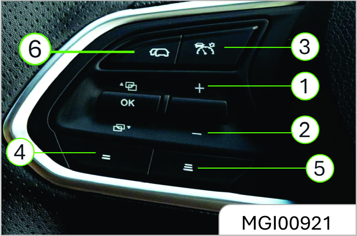
Press the ACC button on steering once to activate the ACC (highlighted by no. 3) Other functions of the ACC switch are as follows
- Speed Limit Increase/ Accelerate
- Speed Limit Decrease/ Decelerate
- Adaptive Cruise Cancel (Single press) & Adaptive Cruise Set
- Decrease Distance
- Increase Distance
- TJA actitation
Enable the Adaptive Cruise Control.
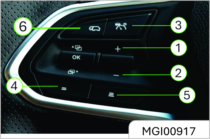
- When the vehicle stands still, it is
required to step on the brake pedal
and then press down the Cruise
ON/OFF button on the steering
wheel (
 ) to activate ACC. Release
the brake pedal and gently step on
the accelerator to start the vehicle.
) to activate ACC. Release
the brake pedal and gently step on
the accelerator to start the vehicle.
- When the vehicle stands still and
without step on the brake pedal,
then press down the Cruise ON/
OFF button on the steering wheel
(
) to Cruise ON/OFF button on
the steering wheel to activate ACC.
The vehicle will reach default cruise
speed that is10km/h.
- When the vehicle is running,
press down the r (
) activate ACC
(Adaptive CruiseControl) with one
button.
- The
 Adaptive Cruise Control
indicator on the instrument turns
blue, indicating that the Adaptive
Cruise Control function is activated
already. The number displayed by
the indicator is the desired vehicle
speed in the mode of cruise.
Adaptive Cruise Control
indicator on the instrument turns
blue, indicating that the Adaptive
Cruise Control function is activated
already. The number displayed by
the indicator is the desired vehicle
speed in the mode of cruise.
The vehicle will automatically accelerate to reach the default cruise speed provided that the Adaptive Cruise Control is activated at a relatively low speed. The default cruise speed is 10 km/h.
The current vehicle speed is deemed as the cruise speed provided that the vehicle speed exceeds the default cruise speed when the Adaptive Cruise Control is activated.
The vehicle will cruise at the expected speed displayed by the instrument provided that there is no vehicle in front when the Adaptive Cruise Control is activated. The vehicle shall follow the vehicle in front by keeping the previously set following time interval if the vehicle in front drives at the slower speed.
Object for Following
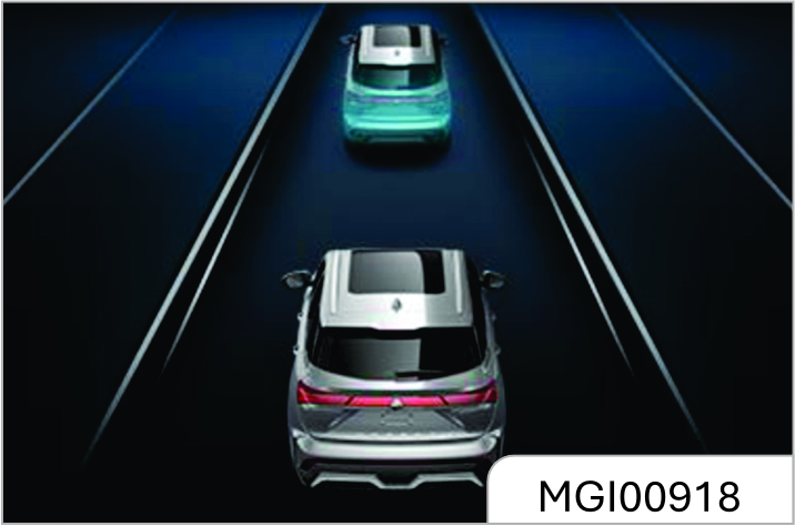
The vehicle in front that is followed by this vehicle will be displayed in the form of blue graphic in the instrument.
If there is no blue graphic displayed to indicate the vehicle in front, it indicates that the Adaptive Cruise Control doesn’t accelerate or decelerate with the vehicle in front. You must actively control the vehicle speed in that circumstance. The system only provides assistance. You must remain cautious in driving and respond proactively all the time.
Adjust the cruise speed
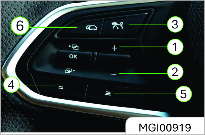
The expected cruise speed is displayed on the combined instrument.
Pullup / down the toggle button to increase / decrease the cruise speed. Adjust to a multiple of 5 for each pull. For example, it will be adjusted to 35Km/h from 31Km/h. The variation of 1km/h will continuously increase or decrease if the button is pressed for a long time. Setting Range: 10-150Km/h.
Set the following time interval
You can adjust the distance from the vehicle in front as required, and the system will use the "following time interval" to indicate the distance. Following time interval refers to the time required to reach the position of the vehicle in front at the current speed.
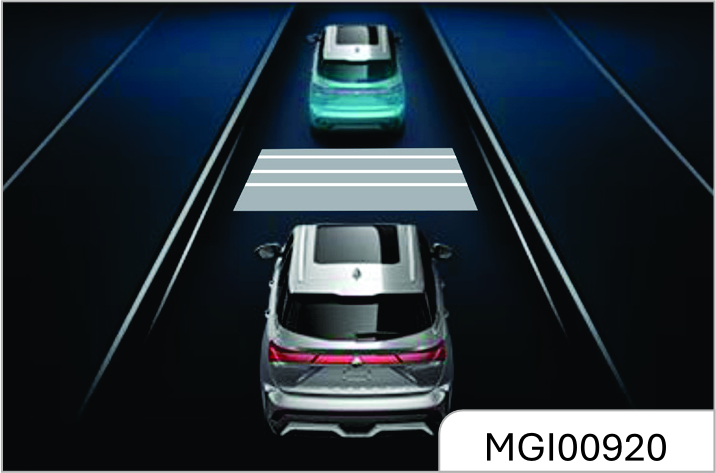
As shown in the figure, there are 7 gear levels for following time intervals, and 1 horizontal line represents 1 gear level. Maximum 2.4 seconds, minimum 1 second. Shorter time is left for the driver for reaction if the following time interval from the vehicle in front is shorter.
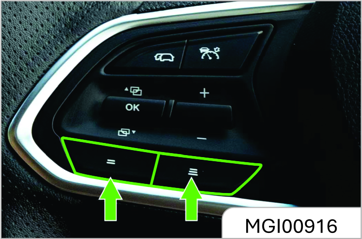
Press the left or right button of the toggle button so as to decrease or increase the following time interval.
Brief Acceleration
You can step on the accelerator to accelerate in the mode of cruise.
- The vehicle will automatically recover the previously set cruise speed once the accelerator is released.
- Push the button toward "-" so as to set the expected cruise speed based on the current speed.
Exit cruise control completely
If the Cruise Control OFF button (
)
is pressed down or the brake pedal is
stepped on, the cruise control system
will be completely disabled and the
indicator light (
) will go out.
Follow the vehicle
The system will control the vehicle which will stop at the proper position behind the vehicle in front provided that the vehicle slowly stops with the vehicle in front. The system will automatically control the vehicle to start with the vehicle in front provided that the vehicle in front will start within 3s. If the vehicle stops for more than 3s, the instrument will display the prompt message "Please gently step on the accelerator so as to resume following the vehicle in front" when the vehicle in front starts. At this time, the driver needs to step on the accelerator gently to resume following the vehicle in front.
Vehicle Takeover
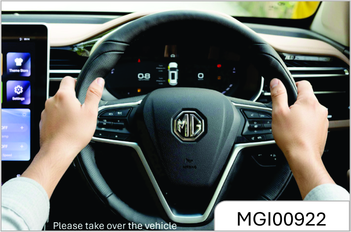
The instrument will give an audible warning and provide prompt message "Please take over the vehicle" when the system has controlled the braking but still unable to maintain a safe distance from the vehicle in front. In that circumstance, the driver must take over the vehicle immediately by performing braking or steering so as to avoid the danger.
Fault Warning Light for Adaptive Cruise Control (ACC)
The warning light that is lit up and turns yellow indicates that any fault exists in the system, which will disable the Adaptive Cruise Control. Please repair it timely.
The Adaptive Cruise Control system cannot be activated in the following circumstances: ESP system is disabled; Door is not closed; Seat belt is not fastened; Gear is not in the position of forward gear; or Electronic Parking Brake is not released, etc.
Descriptions of Adaptive Cruise Control (ACC) Limit
- ACC only works against vehicles in the same lane and running in the same direction. It does not work against vehicle coming from the opposite direction or vehicles moving in the lateral direction, neither the pedestrian, animals or any other objects in the road.
- ACC cannot determine whether the following distance between the vehicle and the vehicle in front is appropriate. The driver must be absolutely vigilant and judge whether there is a potential risk at any time.
- ACC cannot prevent or avoid collision with the vehicle in front. Thus, the driver must immediately control the vehicle and take appropriate measures where necessary for the handling of any danger.
- The radar performance will be greatly reduced in the environment with strong reflection of radar signals (such as parking lot, tunnel, etc.). Please disable the cruise control.
- If the distance between the vehicle and vehicles in the adjacent lane is too small, the vehicle may react and perform braking against that vehicle.
6. The radar may fail to detect the target vehicle in the following circumstances which may result in unexpected acceleration or deceleration and/or the late braking:
- The vehicle runs in a bend or the lane is narrow;
- The vehicle moves left and right when driving in the lane;
- The vehicle in front is equipped with special objects (e.g. objects beyond the side, rear end and roof of the vehicle body);
- Small-size vehicle and/or motorcycle drive in front;
- Vehicle in front has a very high ground clearance;
- The vehicle tilts upward due to excessive weight of the trunk;
- Any other vehicle suddenly enters the lane which may not be detected by the radar if such vehicle doesn’t completely enter the detection range;
- Vehicle in front suddenly moves out, and the radar cannot identify the stationary vehicle in front; or
- The vehicle drives on a ramp.
In principle, the cruise function is applicable to the expressways or totally closed roads. It is prohibited in rainy and snowy days. Cruise driving is also not suitable for winding mountain roads, poor road conditions, environment with dense vehicles or the vehicle being towed.
If a vehicle suddenly drives to the front of the vehicle or the vehicle suddenly moves to the rear of the vehicle in front, the Adaptive Cruise Control may not be able to respond. Please drive cautiously in that circumstance.
- Cruise function is only for auxiliary purpose and cannot completely replace the driver’s control of accelerator and brake. When using this function, you must be cautious and be responsible for judging and actively responding to the traffic conditions. Otherwise, accident may occur.
- If the vehicle in front stands still or moves slowly, the Adaptive Cruise Control may not be able to respond. Please drive cautiously in that circumstance.
Bend Cruise Assist (BCA)*
The system will automatically adjust the vehicle speed based on the size of the bend so as to improve the safety after the Adaptive Cruise Control (ACC) is activated.
If the radius of the bend in front is too small, the Bend Cruise Assist may not be able to reduce the vehicle speed to a safe driving level. Please drive cautiously.
Lane Departure Warning (LDW)*
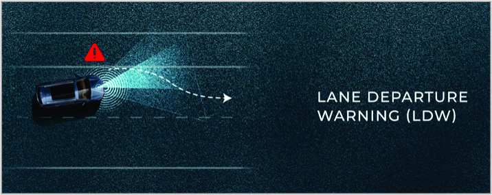
The Lane Departure Warning system detects the lane line in front of the vehicle through the camera sensor. The lane lines are displayed in white on the instrument when the system identifies the lane lines on both sides.
When the vehicle "unconsciously" moves cross the lane marking, for example, you do not turn on the Turn Light or turn the steering wheel intentionally, the vehicle crosses the lane marking. The system will warn the driver through graphic, sound or steering wheel vibration so as to reduce the risk of side collision.
This function is activated when the vehicle speed reaches 60km/h, and disabled when the vehicle speed drops to 55km/h.
You can enable/disable this function in the IVI, and the system will memorize the latest setting. You can also set the sensitivity and reminding mode of Lane Departure Warning in the IVI. The driver can select the warning or alarm mode for the lane departure in the multimedia interface. There are four modes such as "display", "sound", "steering wheel vibration" and "sound + steering wheel vibration"
If the camera fails to detect the lane line, no warning will be given even if the vehicle deviates from the lane.
The Lane Departure Warning system may not work or provide false warning in the following circumstances:
- Poor vision due to factors such as rain, snow, hail, fog, early morning or night, driving in and out of tunnels, etc.
- The view of the camera is blocked by ice, snow and/ or bird droppings on the front windshield.
- The camera is affected by direct light, backlight or lights of the opposite vehicle.
- There is water or snow accumulating on the road surface or the lane line is damaged, blurred or ultra thin.
- Quantity of lanes increases or decreases, or the driving cross the lane lines is of complexity.
- There are more than 2 lane lines on the left and right sides of the lane where the vehicle is driving.
- There are other markings or objects similar to the lines and markings on the road.
- The isolating strips or other objects cast a shadow on the lane lines and markings.
- There is sharp turn or narrow road (lane width>2.5m) or too wide lane.
- The vehicle is too close to the vehicle in front or the vehicle in front blocks the lane line
-
Vehicle shakes violently.
- The Lane Departure Warning is for auxiliary purpose only. Thus, the system cannot effectively identify and respond to the lane lines in any circumstance. The driver must drive cautiously and be responsible for the road condition judgment and safe driving in that circumstance.
- Many unforeseen circumstances will affect the work of Lane Departure Warning or Lane Keeping Assist system. Please check the User Manual in "MY MG" APP.
Lane Keeping Assist (LKA)*
The Lane Keeping Assist system communicates with the camera sensor so as to monitor the lane line on the road ahead and assist you to keep the vehicle in the middle of the lane.
Enable the Lane Keeping Assist
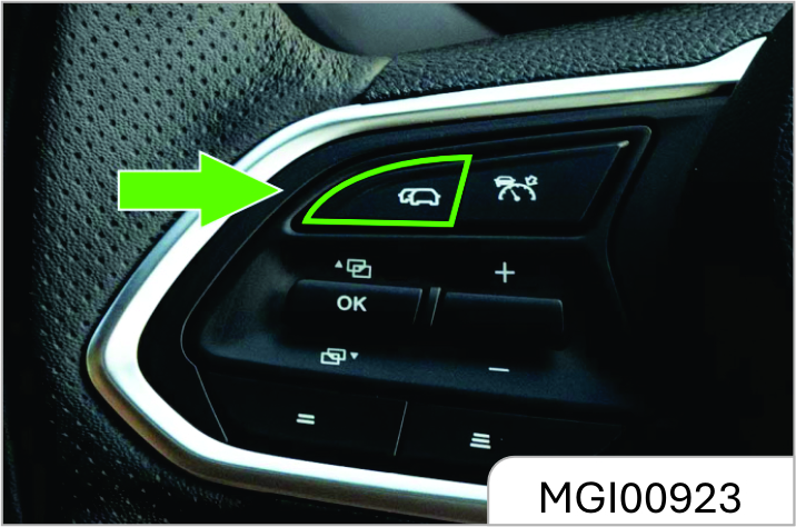
The driver can shortly press down the ON/OFF button on the steering wheel to activate the Lane Keeping Assist. At this time, the indicator light on the combined instrument is lit on, and the lane line turns gray in the indicator light. The system is in standby state.
The Lane Keeping Assist can be activated only when the vehicle speed exceeds 10 km/h.
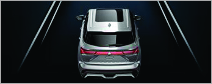
When the system is performing the Lane Keeping Assist, the lane line turns blue in the indicator light on the instrument.
And the lane line in the indicator light ( ) is illuminated and turns green.
There are 2 methods to release Lane Keeping Assist.
- When the vehicle speed drops below 10 km/h, the Lane Keeping Assist will resume the standby state.
- Press down the lane assist switch button on the steering wheel so as to completely disable the lane keeping assist function.
Keep your hands holding the steering wheel.
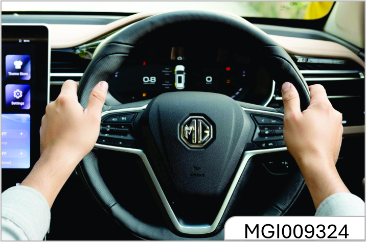
When the system detects that the driver removes his hands from the steering wheel or holds the steering wheel with insufficient force, the system will give a graphic and buzzing reminder via the instrument. Keep your hands holding the steering wheel in any circumstance.
Fault Warning Light for Lane Keeping Assist*
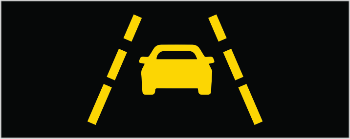
When the indicator light is lit on and turns yellow, it indicates that the system is faulty and cannot provide the Lane Departure Warning or the Lane Keeping Assist. Please repair it timely
The Lane Keeping Assist may not work normally under the following conditions:
- Tyres with dimensions other than those provided by the original manufacturer are used, and/or types equipped with tire chains or snow tires.
- Tyres are excessively worn or the tire pressure is ultra low, and/or the type structure and/or tread pattern are different.
- Use of tyres of other brands and manufacturers may result in the negative impact onto the tyre performance.
- Objects or graphics (e.g. guardrails, curbs, reflective poles, etc.) that may be erroneously identified as white (yellow) separation lines on the roadside.
- Drive on a snow-covered road surface.
- The white (yellow) separation lines are hardly visible due to rain, snow, fog, dust, shadow, etc.
- Road maintenance results in asphalt repai rmarkings, white (yellow) lane separation lines and markings, etc.
- Drive on the temporary lanes or restricted lanes due to road construction.
- Drive on the slippery road surface due to rain, snow, ice, etc.
- Drive on the lane other than the expressway.
- Drive in the construction area.
- It is not recommended for use when towing a trailer or any other vehicle.
- The vehicle drives in area without any white (yellow) separation lines.
- The separation lines are painted yellow (harder to identify compared to the white ones).
- White (Yellow) separation line passes through curbs, etc.
- Drive on a bright or reflective road surface, e.g. concrete.
- Drive at places where the ambient brightness suddenly changes, e.g. the entrance or exit of the tunnel.
- The headlight of the opposite vehicle and/or sunlight enter the camera sensor.
- Drive at the places where the roads diverge or merge.
- Drive on an inclined, winding or bumpy road.
- Drive on a sharp bend section of the road.
- The lanes are particularly narrow or wide.
- The distance from the vehicle in front is particularly short.
- The vehicle bumps up and down violently.
- The headlight cover is stained with dirt and emits weak light at night, or the beam axis deviates.
- The white (yellow) separation line is broken, or there are cat eyes (reflective signs) or stones.
- The vehicle is exposed to crosswind.
- The vehicle just changes lanes or passed through intersections.
The Automatic Lane Keeping is for auxiliary purpose only. Thus, the system cannot effectively identify the lane lines and provide the assistance in any circumstance The driver must drive cautiously and be responsible forjudging and actively responding to the traffic conditions. Otherwise, accident may occur.
Traffic Jam Assist (TJA)*
The Traffic Jam Assist may keep the vehicle driving in the middle of the lane line and keep a safe distance from the vehicle in front within the speed range of 0-60km/h.
Enable the Traffic Jam Assist.
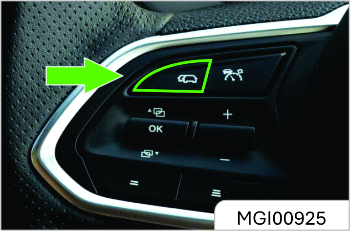
Shortly press down and hold the ON/
OFF button (
 ) to enable the Traffic Jam
Assist.
) to enable the Traffic Jam
Assist.
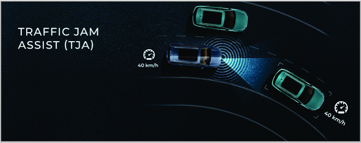
If the system identifies the lane lines on
both sides, the Traffic Jam Assist will be
activated and the lane lines displayed
by the instrument will turn blue (as
shown in the Figure above). In this
circumstance, the vehicle will drive in
the middle of the lane line. At the same
time, the vehicle and lane lines in the
indicative graphic signs for lane keeping
(
) are displayed green.
After the traffic jam assist is enabled, the Adaptive Cruise Control will be activated automatically. You can adjust the vehicle speed and the following time interval.
Please refer to the Chapter "Adaptive Cruise Control (ACC)" above.
Release the Traffic Jam Assist
The Traffic Jam Assist can be released through the following ways:
- Step on the brake pedal so as to disable the Adaptive Cruise Control and resume the standby status.
- Press down ON/OFF button (
 )
to disable the Traffic Jam Assist.
)
to disable the Traffic Jam Assist.
-
Press down the cruise ON/OFF
button (
) to disable the cruise
function.
- Press the Lane Keeping Assist ON/ OFF button on the steering wheel to disable the Lane Keeping Assist
Resume the Traffic Jam Assist.
- You can shortly press down and
hold the switch (
) to re-enable
the Traffic Jam Assist.
High-speed Intelligent Cruise Assist (ICA)* The high-speed Intelligent Cruise Assist can keep the vehicle driving in the
middle of the lane line and keep a safe distance from the vehicle in front within the speed range of 60-150 km/h.
Please refer to the Chapter - Traffic Jam Assist for the use of high-speed Intelligent Cruise Assist.
It is recommended to enable the Traffic Jam Assist or highspeed Intelligent Cruise Assist when the vehicle drives on the relatively closed roads in good conditions such as expressways, urban expressways, etc. It is not recommended to be used when the vehicle drives in the environment such as urban areas, mountain roads, ramps, etc.
Keep your hands holding the steering wheel. The driver must actively control the driving direction. Otherwise danger may occur.
Traffic Jam Assist and high-speed Intelligent Cruise Assist will not realize automatic driving. Any restrictions affecting the Adaptive Cruise Control and the Lane Keeping Assist will affect the performance. You must remain cautious and proactively judge and respond to the traffic conditions. Otherwise, accident may occur.
Safe Distance Warning (SDW)*
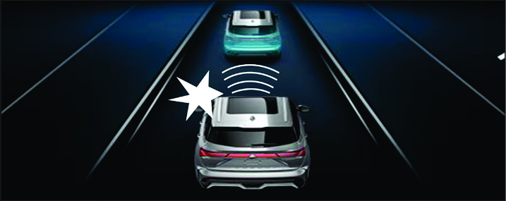
The Safe Distance Warning detects the vehicle in front via radar and provides the prompt message in the instrument in case of too-close distance between the vehicle and the vehicle in front.
Conditions for Working of the Function:
- The vehicle speed is maintained between 65- 150 km/h;
The Forward Collision Warning system can detect the potential front collision hazard and provide prompt message to remind the driver of such collision so that the driver can respond to avoid or mitigate such collision.
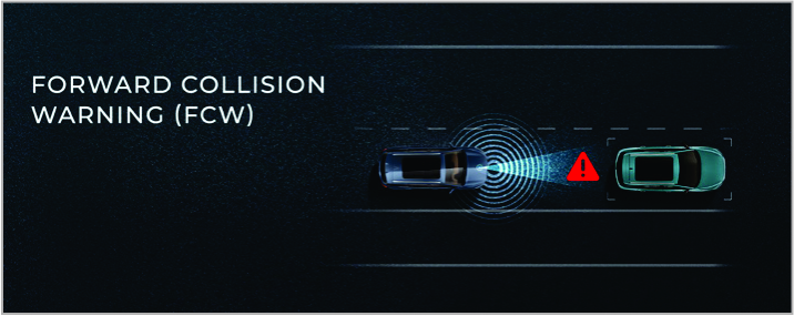
As shown in the figure, the combined instrument will give audible and graphic warning when the system detects any potential collision hazard.
If the situation continuously turns for worse, the system will apply short time braking so as to warn the driver.
You can adjust the sensitivity of the Forward Collision Warning in the IVI or disable this function temporarily.
The Forward Collision Warn in system cannot detect the following conditions. Please drive with caution:
- Vehicles running on the same lane.
The Foward Collision Warning system will work at different vehicle speed in regards of different objects. The driver shall drive cautiously: If the target is a moving vehicle, the working speed is 30-150 km/h. If the target is a vehicle standing still, the working speed is 30-85 km/h. If the target is a pedestrian walking laterally; the working speed is 30- 65km/h.
The Forward Collision Warning system will not respond in the following circumstances. The driver shall drive cautiously:
- Vehicle speed is out of working range.
- The driver makes a great active steering.
- The Driver steps down the accelerator quickly and forcibly in an substantive way.
- Disable the Forward Collision Warning system or the Body Stability System.
- The vehicle is out of stability.
- The radar is blocked.
- The Forward Collision Warning is for instructive purpose only. The system cannot always effectively remind the driver to avoid the collision in any circumstance. Thus, the driver shall drive cautiously and be responsible for judging the road conditions.
- The Forward Collision Warning system only provides reminder and will not brake. The driver must immediately control the vehicle once the system makes a warning.
Automatic Emergency Brake (AEB)*
The automatic emergency braking system will automatically apply limited braking to reduce the vehicle speed for the purpose of avoiding collision or mitigating its consequences if the driver does not respond when approaching a collision.
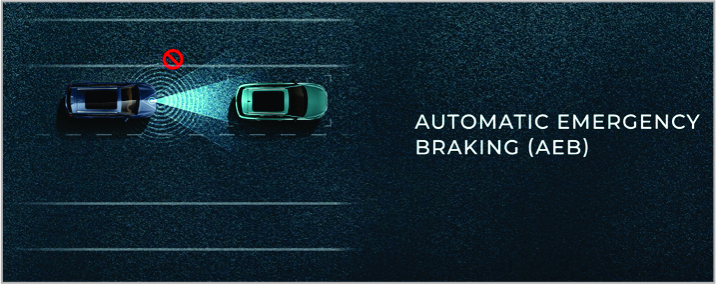
As shown in the figure, the instrument will display the warning graphics and text and make a rapid audible warning when the system is automatically braking.
Indicator Light for Automatic Emergency Brake OFF

You can temporarily disable the Automatic Emergency Brak e i n t he IVI ( not recommended). The instrument will light up the indicator light if this function is disabled.
Fault Warning Light for Forward Collision Warning and Automatic Emergency Brake*
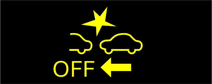
The indicator light turns yellow.
When the warning light is on, it indicates that the Forward Collision Warning or the Automatic Emergency Brake system is faulty and cannot provide any forward collision warning and braking related assistance. Please drive the vehicle cautiously and repair the vehicle as soon as possible.
The Automatic Emergency Brake system will work at different vehicle speeds in regards of different objects. The driver shall drive cautiously:
If the target is a moving vehicle, the working speed is 7-150 km/h. If the target is a vehicle standing still, the working speed is 7-85 km/h. If the target is a pedestrian walking laterally, the working speed is 7-65km/h.
The Automatic Emergency Brake system is prohibited in the following circumstances:
- The vehicle is being towed or towing any other vehicles.
- The vehicle is on a rotating hub test bench.
- The vehicle performs any unconventional driving such as competition, cross-country driving, etc.
- The tire pressure is not within the standard value.
- Tyres are seriously worn.
- The vehicle are equipped with tyres of dimensions other than the original ones.
- Tyres are equipped with the tyre chain.
- The suspension height is not within the normal range, modified or overloaded.
The Automatic Emergency Brake may be insufficient in the following circumstances.
The driver shall drive cautiously:
- The brake disc is overheated, overcooled or humid, preventing the braking function from the performance of its maximum extent.
- The vehicle is not properly maintained (e.g. excessive wear of brake or tyre, incorrect tyre pressure, etc.).
- The vehicle drives on slippery or soft road surface or any other slippery road.
The Automatic Emergency Brake system may fail in the following circumstances. The driver shall drive cautiously:
- Objects carried by the vehicle in front are beyond the rear bumper.
- The ground clearance of the vehicle in front is extremely high.
- The vehicle in front is irregularly shaped,e.g. tractor or trolley.
- The vehicle in front is directly exposed to sunlight or any other ray of light.
- Any vehicle moves out from the front of the vehicle or appears from the side of any other vehicle.
- The vehicle in front performs unexpected operations, e.g.emergency steering, acceleration or deceleration.
- The vehicle suddenly move to the rear of the vehicle in front.
- The vehicle drives on a slippery road surface in severe weather, such as rainstorm, fog, snow or sandstorm.
- The front of the vehicle rises or lowers in the environment where the road surface is uneven or undulates.
- The headlights are modified.
- The brake disc is overheated, overcooled or humid.
- There is a large wall or plain color object standing in front.
The Automatic Emergency Brake system does not work in the following circumstances. The driver shall drive cautiously:
- The ESP system is manually disabled or fails.
- The vehicle is out of stability.
- The radar sensor is stained with dirt or covered.
- The system may determine the driver is taking any avoidance measure and prevent the AEB brake function from working (even if the AEB system’s automatic braking function is working) provided that the driver steps on the accelerator with force or turns the steering wheel.
- Other vehicle comes from the opposite direction.
- The vehicle in front is not in the due front of the vehicle.
- The vehicle speed is not in AEB working range.
Automatic Emergency Brake can prevent collision or reduce collision speed.
When the system sensor detects any potential collision, it will automatically brake. The driver can step on the brake pedal so as to obtain sufficient braking force. However, the Automatic Emergency Brake system will be disabled if the driver steps on the accelerator or takes steering intervention during the function triggering process.AEB will get deactivated if any pedal is pressed or steering maneuver is detected.
In addition, the driver needs to step on the brake pedal with great force when this function triggers automatic braking.
The Automatic Emergency Brake may be triggered by mistake in the following circumstances. The driver shall drive cautiously.
- The vehicle is approaching the vehicle in front that is turning left, right or changing lanes.
- The vehicle drives past the vehicle coming from the opposite direction that is ready for turning right or left.
- The vehicle in front on the adjacent lane is detected due to the curve of the road.
- The front of the vehicle rises or lowers in the environment where the road surface is uneven or undulates.
- The vehicle is approaching roadside objects, such as guardrails, poles, trees or walls.
- There are vehicles, pedestrians or objects at the roadside of the entrance of the bend.
- The vehicle is driving on narrow roads surrounded by building structures, such as tunnels or iron bridges.
- The vehicle may bump into metal objects (well covers, steel plates, etc.) on the road surface or by side of the road, steps or protrusions.
- Pedestrians crossing the street are very close to the vehicle.
- There are small-size vehicles in front, e.g. motorcycles, bicycles, etc.
- The vehicle in front has a small rear end, e.g. unloaded truck.
- The rear end of the vehicle in front is low, e.g. tractor trailer.
- The vehicle is driving through steam or smoke area.
- The vehicle is driving in the environment where the ambient brightness suddenly changes, such as the entrance or exit of the tunnel.
In any circumstance, the driver is always responsible for maintaining the normal distance and driving speed, and is responsible for the way of driving and avoidance of dangerous situations. The driver must always focus on driving with great caution.
The Automatic Emergency Brake system does not always reach the same performance level based on different vehicles, scenarios and road conditions.
Many unforeseen conditions will affect the work of the system. Please check the User Manual in "MY MG" APP.
- The vehicle is driving on the road where there is a low structure above the road (e.g. low roof, tunnel height limit sign, highspeed toll station railing, parking area railing, automatic car washing room, etc.).
- The vehicle is driving beneath objects (e.g. billboards, etc.) at the top of the uphill road.
- The vehicle is driving between or beneath objects that may contact the vehicle, e.g. dense grass, branches or banners.
- The vehicle is driving between or beneath objects that may contact the vehicle, e.g. dense grass, branches or banners.
- The vehicle is driving through steam or smoke area.
- The graphics or paint on the road or wall may be erroneously identified as vehicle or pedestrian.
- The vehicle is approaching objects reflecting radio waves, e.g. large-size truck or guardrail.
- The vehicle is approaching television towers, radio stations, power plants or any other places that may emit strong radio waves or electrical noise interference.
In addition, there may be some other complicated driving environments, which may cause unnecessary braking of the system.
If the Automatic Emergency Brake system completely stops the vehicle, the system will automatically release the brake after stopping for 2 seconds. At this time, the vehicle is not braked, and the driver must step on the brake pedal or pull up the handbrake.
AEB cannot be relied upon too much: The Automatic Emergency Brake system can assist the driver in driving in particularly dangerous situations, but cannot replace the driver’s judgment of road and traffic conditions, let alone the driver’s control of the vehicle. The driver cannot rely too much on this function during driving. The Company is not responsible for any consequences arising from reliance on this system.
Prohibition of Testing:
The Automatic Emergency Brake system is only a safety assistance function, and any automatic system cannot ensure 100% normal working under all conditions. Thus, it is forbidden to drive the vehicle towards pedestrians, animals or any other vehicles for the purpose of system testing, which may cause serious losses or casualties.
Pedestrian Identification* (equipped for models with camera sensors)
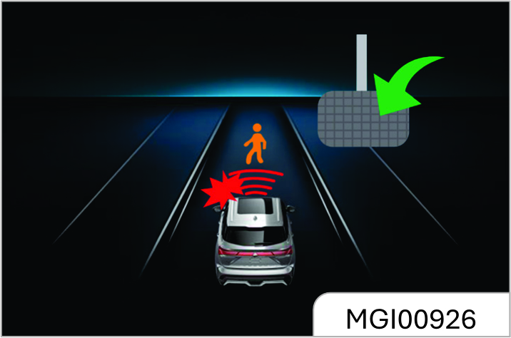
If the vehicle is equipped with a camera sensor (see section "Radar and Camera Sensor* above), its Forward Collision Warning and Automatic Emergency Brake system can identify moving pedestrians crossing the road under specific conditions.
The system will give an audible warning and the instrument will display "Brake Requested" when the vehicle speed is within the range of 7-64km/h and the pedestrian collision risk is detected.
When the vehicle speed is within the range of 7- 64 km/h, the system w ill autom atically apply emergency braking so as to mitigate or avoid collision if the driver does not take measures against the pedestrian collision warning.
Note that the system can only identify pedestrians who cross the road and are walking, and cannot identify pedestrians who are walking along the road or standing still.
Due to the influence of ambient brightness, or pedestrian walking posture and angle, the system may not be able to identify and respond to pedestrians. The driver shall drive cautiously.
The pedestrians may not be detected by radar sensors and cameras in the following circumstances:
- Height of the pedestrian is less than 1m or higher than 2m.
- The pedestrian wears oversized clothes (e.g. raincoat or long skirt) which blur his or her outline.
- The pedestrian carries large luggage, umbrellas, etc. which cover some parts of the body of such pedestrian.
- The pedestrian is bending forward or squatting down.
- The pedestrian is pushing stroller, wheelchair, bicycle or any other vehicle.
- Pedestrians are walking in crowds
- Under backlight and o ther l ight conditions, the system may not be able to identify pedestrian wearing white clothes or other pedestrian of which the light color and/or brightness looking close to the ambient light color and/or brightness.
- Pedestrian is in dark places, such as at night or in tunnels.
- Pedestrian wears clothes that almost have the same color or brightness as that of the surrounding environment.
- Pedestrian is near walls, fences, guardrails or large objects.
- Pedestrian stands on metal objects (e.g. well covers, steel plates, etc.) on the road.
- Pedestrian walks fast.
- Pedestrian changes walking speed suddenly.
- Pedestrian runs out from the place behind the vehicle or any other large objects.
- Pedestrian is very close to the side of the vehicle (e.g. exterior rearview mirrors, etc.).
2.6 Reverse Sensor*
The intelligent reverse sensor judges the distance between rear end of the vehicle and the obstacle via the ultrasonic transducer installed on the rear bumper.
If the buzzer buzzes once after you turn on the ignition switch and shift to reverse gear, it indicates that the system can work normally.
If the buzzer buzzes twice, it indicates that one transducer fails to work; if it buzzes thrice, it indicates that 2 or more transducers cannot work normally.
The intelligent reverse sensor starts to work immediately every time you turn on the ignition switch and shift to reverse gear.
When the distance between the vehicle and the obstacle behind it is within about 1.5 m~1.0 m, the reverse buzzer sends out alarm sound at long intervals.
When the distance between the vehicle and the obstacle behind it is within about 1.0 m~0.6 m, the reverse buzzer sends out alarm sound at short intervals.
When the distance between the vehicle and the obstacle behind it is within about 0.6 m~0.4 m, the reverse buzzer sends out alarm sound at shorter intervals.
When the distance between the vehicle and the obstacle behind it is within about 0.4 m, the reverse buzzer sends out alarm sound constantly.
- Please note that the system is likely to work abnormally due to wrong induction under the following circumstances: reversing the vehicle on an uneven road, a road paved with round stones, an uphill road or grassland; interference from ultrasonic noise, metallic sound or highpressure gas emission sound of the same frequency; sundries on the transducers; height change of vehicle rear end under heavy load; other detecting equipment installed within the effective detection range.
- If any nonstandard radio communication equipment is installed on the vehicle, usage of such equipment (not including mobile cellphone and audio system) may affect the function of this system.
To ensure reversing safety and to leave enough time for the system to detect, please drive at a speed of 5 km/h or lower during reversing.
Please stop the vehicle immediately a constant alarm sound is heard in case that the vehicle bumps onto the obstacle behind it.
Please do not knock the transducers hard or wash them directly with a high- pressure water gun, otherwise the transducers can be damaged.
Sundries on the transducers such as snow, mud and water drops can lead to mis operation.
Please note that the system is likely to fail to detect the following obstacles: those of a conical shape or acute angle reflectors; objects which are prone to absorb sound wave, such as cotton and snow; fine objects such as iron gauze and ropes; objects 30 cm or lower to the ground or 1m or higher than the ground. The system may detect these obstacles first, but as they become nearer and nearer to the vehicle, they can get out of the effective detection range, not detected as a result.
When reversing down or up a slope, the system may give out a wrong warning, reminding you to take great care.
Reverse Video Display*
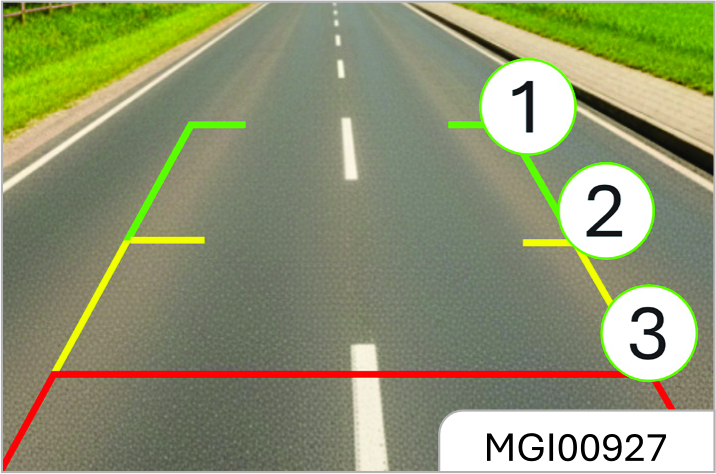
As is shown in the figure, if the vehicle is equipped with reverse camera, images behind the vehicle, reverse auxiliary lines and guide lines will appear on the multimedia player screen after you turn on the ignition switch, release the parking brake and shift to Reverse Gear "R". If the vehicle is of high configuration, a sector indication area will also show on the screen.
Reverse Auxiliary Line
The auxiliary is divided into three sections: red, yellow and green, based on the distance between the object and rear end of the vehicle.
The bottom red line represents the warning line for a distance front the obstacle to the vehicle rear end within 0.4 m; the middle yellow line represents the warning line for a distance from the obstacle to the vehicle rear end within 1.0 m; the top green line represents the warning line for a distance the obstacle to the vehicle rear end within 2.0 m; the line on both sides is the vehicle width indication line.
Reverse Guide Line*
The yellow guide line can develop into a dynamic virtual guiding line as you turn the steering wheel.
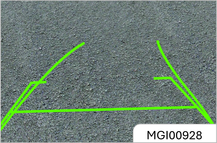
Sector Indication Area*
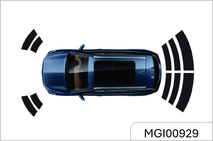
As is shown in the figure, a total of 6 sector indication areas are shown on the screen, indicating the distance from the obstacle to front left, front right, rear left, rear right, rear left middle and rear right middle of the vehicle respectively.
For the front left, front right, rear left and rear right sector indication areas:
When the distance from the vehicle to the obstacle is within about 0.4 m~0.6 m, the sector indication area appears yellow and the buzzer sends out alarm sound at short intervals. When the distance is within 0.4 m, the sector indication area appears red and the buzzer sends out alarm sound constantly
For the rear left middle and rear right middle sector indication areas: When the distance from the vehicle to the obstacle is within about 0.6 m ~ 1.0 m, the sector indication area appears green and the buzzer sends out alarm sound intermittently. When the distance is within 0.4 m~0.6 m, the sector indication area appears yellow and the buzzer sends out alarm sound at short intervals. When the distance is within 0.4 m, the sector indication area appears red and the buzzer sends out alarm sound constantly.
The intelligent reverse camera can only help the driver avoid accident during reversing. The driver should always keep concentrated. JSW MG Motor shoulders no responsibility for any personal injury or vehicle damage resulting from careless driving with great reliance on the on- board reverse camera. Before reversing, please ensure that no child or animal is near the vehicle.
Parking Assist System*
The parking assist system judges the distance between front/rear end of the vehicle and the obstacle via the ultrasonic transducer installed on the front/rear bumper. If the buzzer buzzes once after you turn on the ignition switch, it indicates that the system can work normally.
If the buzzer buzzes twice, it indicates that one transducer fails to work; if it buzzes thrice, it indicates that 2 or more transducers cannot work normally.
When a transducer fault is detected, the fault information will appear on the audio system display screen.
The reverse camera and the parking assist system can only help the driver avoid accident during reversing or parking. The driver should always keep concentrated. JSW MG Motor shoulders no responsibility for any personal injury or vehicle damage resulting from careless driving with great reliance on the on- board radar system. Before reversing or parking, please ensure that no child or animal is near the vehicle as the radar system may fail to respond to them.
2.7 Parking Assist System Switch Type I*
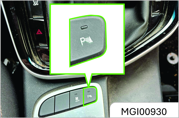
Parking Assist System Switch Type II*
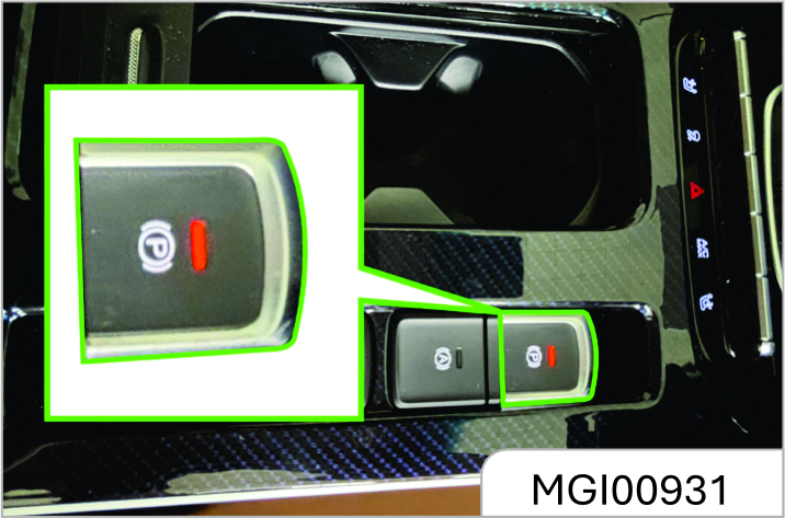
If the vehicle is equipped with parking assist system switch, the switch indicator will illuminate after the ignition switch is turned on and the parking assist system switch is pressed; if the parking brake is released at this time, the parking assist system starts to work.
If front/rear end of the vehicle is within certain distance from the obstacle, parking assist indication will appear on the audio system display screen. Press the switch again and the parking assist system turns off. The switch indicator also goes out.
The parking assist system activates automatically (under the precondition that the parking brake is released) as the shift lever is turned to the reverse gear.
It exits when the vehicle speed exceeds 20 km/h. To activate the system again, please press the switch.
Parking System Display*
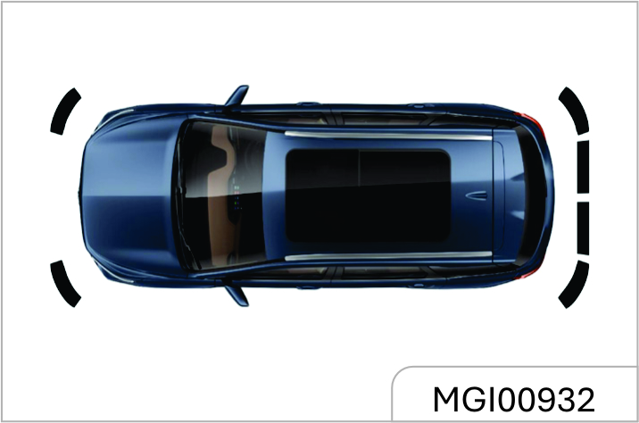
As is shown in the figure, when the transmission is engaged on the Forward Gear (D Mode) or the Neutral Gear, a prompt window will pop up in the audio system display screen as front end of the vehicle is within about 0.6 m from the obstacle or rear end of the vehicle is within about 1.5 m from the obstacle.
Color of the front and rear sector areas will change as the distance changes, accompanied by alarm sound. Please refer to information given in "Sector Indication Area".
The prompt window will disappear when the system detects no obstacle.
The window will disappear immediately you press the window off button (x). It will appear again if an obstacle is detected.
360 Degree Panoramic Parking Screen Assist* Type 1
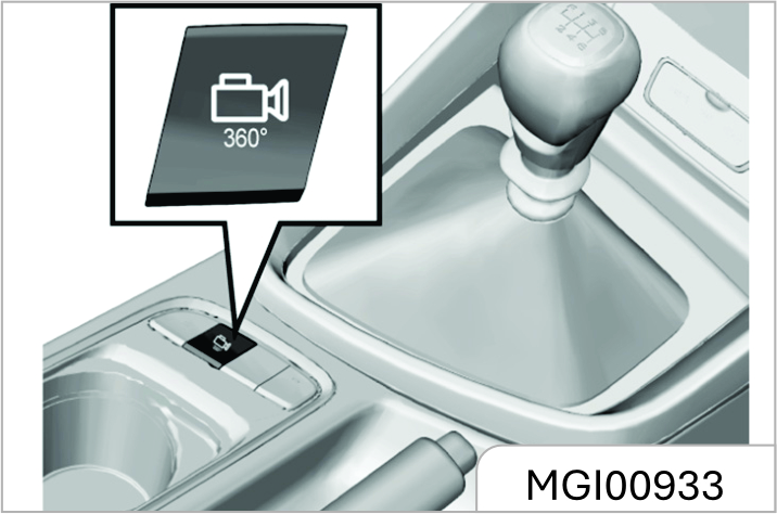
360 Degree Panoramic Parking Screen Assist* Type 2
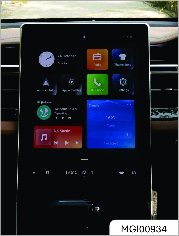
The 360° panoramic parking image assist is to display the images collected by the cameras installed on both sides of the outside rearview mirrors and
the front/rear bumpers on the display screen of the audio system to help you check the outside environment. Turn the ignition switch at the ON position before using this function. It exits when the vehicle speed exceeds 20 km/h.
When the transmission is at Forward Gear (D Mode) or Neutral Gear, press the switch to display the 360° panoramic parking image assist. When the transmission is at R gear, this function is enabled automatically
Panoramic Parking Screen Switch
When the transmission is engaged in Forward Gear (D Mode) or Neutral Gear, press ON / OFF switch to display 360 degree parking screen auxiliary function.
It is automatically turned on when the Reverse Gear (R) is engaged. Under the parking assist screen, according to your needs, Tap the screen selection icon on the left side of the center console to cut change to the corresponding interface below. Using left / right indicators can also change interface view.
Parking Image Assist during Reversing
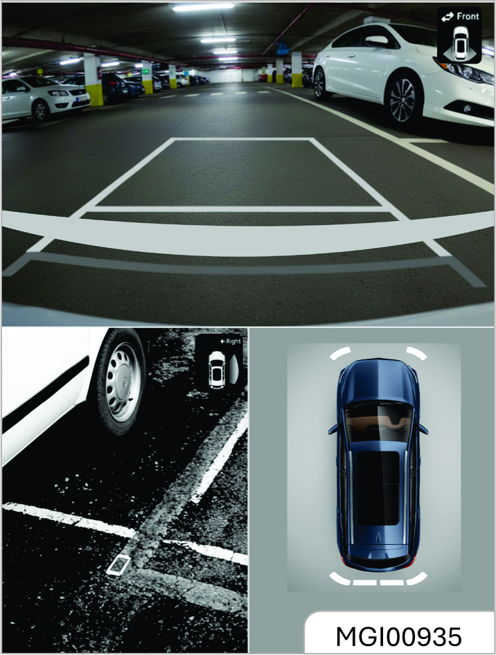
When the transmission is turned to R gear, the "rear view + side view + 3D panoramic view" will appear on the display screen of the audio system to help you check the environment behind the vehicle when reversing.
Parking Image Assist at Forward Gear (D Mode) or Neutral Gear
When the transmission is at Neutral Gear or Forward Gear (D Mo de), if you want to check the environment in front of the vehicle, press the panoramic parking image switch to display the "front view + side view + 3D panoramic view".
Parking Image Assist during Reversing
If you need to check the side environment during turning, press the switch first and then turn on the turn signal lamp to display the "front/rear view + side view + 3D panoramic view" on the display screen of the audio system.
You can also press the keys on the screen to switch the images.
There is a certain blind spot in the parking screen, especially near the area around the vehicle. Therefore, it must be cautious, not to use this function as the only basis for judging safety.
MG India is not responsible for any inadvertent driving if assisted by the parking screen of the device cause personal injury and property damage.
Comfort & Convenience
3.1 Rear View Mirrors
3.1.1 Outside Rear View Mirror
Please check the visual field of all rearview mirrors before driving.
Adjusting Outside Rearview Mirror
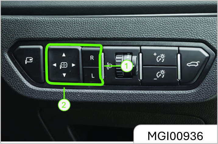
The power outside rearview mirror adjustment switch is on the left side of the instrument panel. Adjust the outside rearview mirror as per the following steps:
- Select the rearview mirror to be adjusted. Press the "L" or "R" on the selector switch to adjust the left or right outside rearview mirror.
- Press the buttons(
 )around the
setting pan to adjust the selected
rearview mirror upward, downward,
leftward and rightward.
)around the
setting pan to adjust the selected
rearview mirror upward, downward,
leftward and rightward.
- After adjustment, recover the selector switch to non-pressed state (both ends not pressed).
Electrically Folding Outside Rearview Mirror*
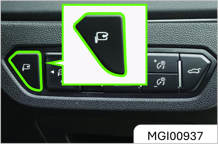
Press the electric folding button to fold the outside rearview mirror automatically.
Press the button once again, and the mirror will unfold automatically.
Automatically Folding Outside Rearview Mirror*
The outside rearview mirror will be folded automatically when the doors are locked. It will unfold automatically when the doors are unlocked.
If the electric folding button is pressed, the outside rearview mirror will not be unfolded automatically when the doors are unlocked.
Deactivating Automatic Folding Function of Outside Rearview Mirror*
In frosty weather, the outside rearview mirror and its spindle may be frozen in folded state, and the mirror cannot be unfolded. That will affect your driving. Therefore, we suggest you deactivate
the automatic folding function of the outside rearview mirror temporarily in icy winter to let the mirror maintained in unfolded state.
Method: Enter the Setting Mode Auto ORVM and set to "OFF". Thus, the outside rearview mirror will not be folded automatically when the doors are locked.
Notes to Electrical Folding of Frozen Outside Rearview Mirror
If the outside rearview mirror and its spindle are frozen, please remove the freeze first, and use the electric folding/ unfolding functions. For example, if the mirror is frozen after the vehicle is parked outdoors for a night in winter, please remove the freeze first, and use the remote control or the passive entry button to unlock doors. Then, the outside rearview mirror will be unfolded smoothly. If the freeze is not removed, the freeze will hinder the movement of the rearview mirror, damaging the mirror.
If the outside rearview mirror glass is frozen, please remove the freeze first, and then use the defrosting function for auxiliary heating and deicing. If the freeze is not removed, the freeze will hinder the movement of the rearview mirror while adjusting the mirror, causing damage to the mirror.
Folding
To ensure the pedestrian’s safety, the outside rearview mirror can be folded forward or backward from its normal mounting position under sufficient impact force. It can be moved and reset manually.
Defrosting of Outside Rearview Mirror*
The outside rearview mirror of some models is configured with defrosting function. Press the rear defrost button on the A/C control panel for defrosting. Refer to the content of the rear defrost button in the Chapter "HVAC".
The anti-dazzling mode will reduce the vision clarity behind the vehicle. Please drive carefully.
3.1.2 Inside Rearview Mirror
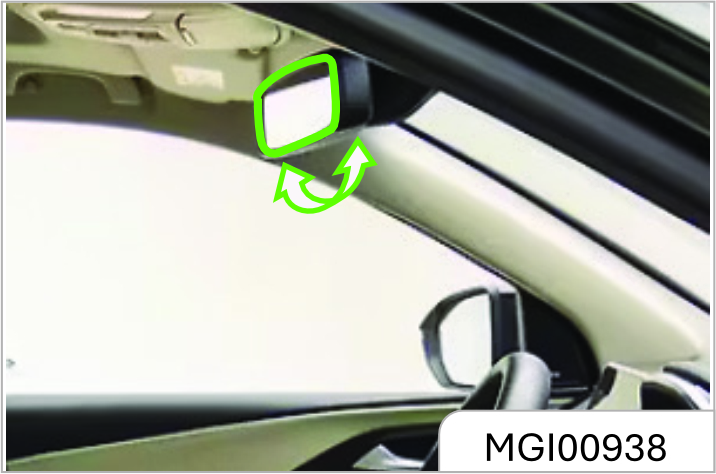
Adjust the rearview mirror to an appropriate angle manually. The rearview mirror of some models has anti-dazzling function which can reduce the dazzling effect from vehicles behind at night. Turn the switch at the rearview mirror bottom forward to activate the anti-dazzling mode. Please remember to turn the switch back in the daytime.
3.2 Windows
Power Window
When the ignition switch is at ON position, you can control the power window with the power window switch on the door armrest panel. You can also use the combination switch on the driver’s side to control other power windows.
The windows can also be controlled with the power window switches within 30s after the ignition switch is turned from ON position to ACC or LOCK position or the key is pulled out.
Children may operate the ower window and may get stuck by the window when they operate it.
Do not leave a key or an unattended child in the vehicle. Misoperation of the power window may cause casualties.
Power Window Switch
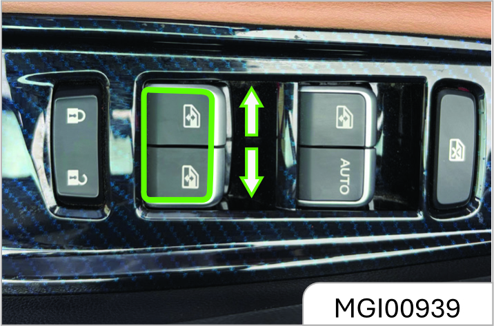
To raise the window, pull upward the switch. To lower the window, press down the switch.
When the window reaches the desired position, release the switch.
If an occupant stretch his / her body out of the vehicle, he/she may be hit by objects passing by.
Do not stretch any body part out of the vehicle.
One-button Lowering of Driver’s Side Power Window
The driver’s side power window has the onebutton lowering function. Press the switch to the bottom and release, and the window will be lowered to the fullyopen position automatically. To stop lowering the window, pull upward the button and release (short pull is ok).
One-button Rising of Driver’s Side Power Window*
The driver’s side power window of some models has the one-button raising function. To close the window, pull upward the switch to the top and release, and the window will be raised automatically to the fully-close position. To stop raising the window, press down the button and release (short press is ok).
Anti-pinch Function of Driver’s Side Power Window*
The power window that has the onebutton rising function also has the anti-pinch function to reduce pinching injuries. The power window will be lowered automatically for a distance in case of any obstruction in its one button rising process.
Remote Lowering of Power Window
Press and hold the unlock button on the remote-control key for about 2s to lower all window glass in turn.
Initialization Learning of Driver’s Side Power Window*
The driver’s side window may lose one button rising and lowering functions in some cases, such as battery connection after disconnection. In case of such outage, the window initialization learning shall be conducted first. First, pull upward the driver’s side switch till the window glass is closed completely, and continue to pull upward the switch for at least 5s and release it. Now the initialization of learning is completed. If the one button raising or lowering function is still unavailable after initializing learning, it is recommended to drive to the JSW MG Authorized Service Center for check and repair.
Power Window Lock Button
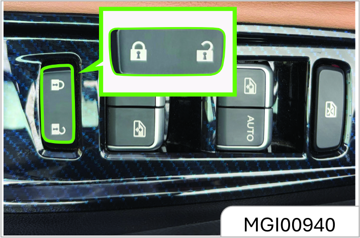
The power window lock button can lock the front passenger’s side and rear power window switches. Press the button, and other power window switches are locked. The windows can only be operated with the driver’s side window control panel.
Press the button once again, and the lock can be released.
Children may operate the power window and may get stuck by the window when they operate it or may get out of the vehicle from the window, leading severe causalities. Please use the power window lock when there is a child in the vehicle.
Sunshade
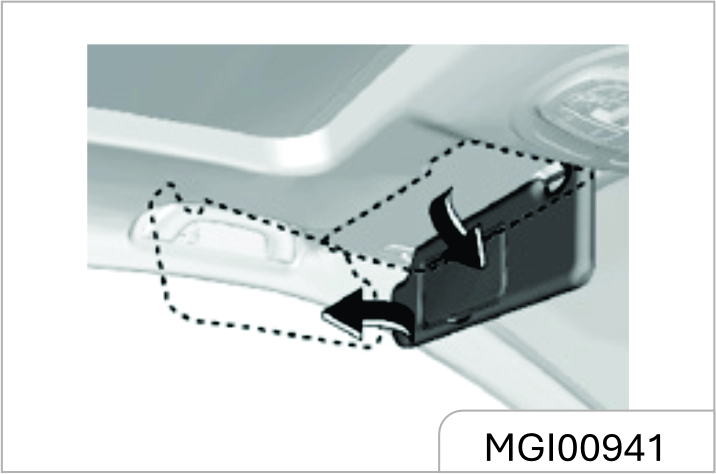
Your vehicle is configured with sunshade which can reduce dazzling effect on the driver and passengers.
The sunshade can move upward, downward and sideward.
Depending on the configuration, the sunshade may be equipped with a bill fold and vanity mirror.
Auxiliary Handrail
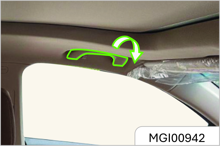
Above the front passenger’s side door and rear doors, an auxiliary handrail is installed. The handrail of some models is equipped with a clothes hook.
The auxiliary handrail is convenient for passengers to get in and out of the vehicle. The passengers can also grab the handrail to help maintain the sitting position when the vehicle speed is fast
While using the auxiliary handrail, hold it downward. When it is released, it will return automatically.
3.3 Sunroof*
Always observe the following notes:
- Do not stretch out the body or any object out of the sunroof.
- Please ensure that there is no object in and out of the sunroof before the sunroof is opened or closed.
- Do not place a heavy object on or around the sunroof.
- Make sure that there is no rubbish on the outer side of the sunroof.
- When the vehicle is left unattended, the sunroof must be closed.
All occupants must buckle seat belts in all cases no matter whether the sunroof is opened or closed.
If the notes above are not observed, severe injuries or vehicle damage will be caused.
When the ignition switch is at ON position, the power sunroof can be operated.
Power Sunroof*
Sunroof Sliding
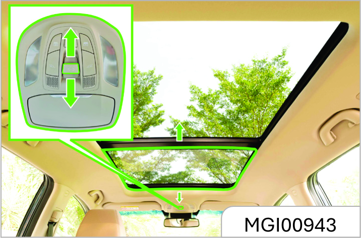
- To slide open the sunroof, push the rear end of the switch once quickly and release (operate within 0.3s). After the sunroof reaches the desired position, push the front end or rear end of the switch again, or push and hold the rear end, and release the switch after the sunroof reaches the desired position.
- To slide close the sunroof, push and hold the front end of the switch, and release the switch when the sunroof reaches the desired position but is not completely closed. To completely close the sunroof, push and hold the front end of the switch, and release the switch when the sunroof stops moving, or push the front end of the switch once quickly and then release (operate within 0.3s).
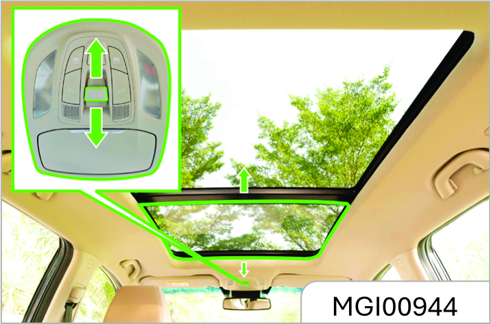
Sunroof Tilting
- To tilt open the sunroof, press the front end of the switch when the sunroof is completely closed, and release the switch when the sunroof reaches the desired position. To completely tilt the sunroof, press and hold the front end of the switch, and release the switch when the sunroof stops moving, or press the front end of the switch once quickly (operate within 0.3s).
- To completely close the tilted sunroof, press and hold the rear end of the switch, and release the switch when the sunroof reaches the desired position but is not completely closed. To completely close the sunroof, release the switch when the sunroof stops moving, or press the rear end of the switch once quickly and then release (operate within 0.3s).
One-button Opening or Closing of Sunroof
While operating the sunroof switch, you can press the front or rear end of the switch once quickly (operate within 0.3s), and the sunroof will be closed or opened automatically.
Sunroof Anti-pinch Function
The sunroof will retract to prevent pinching persons when it contacts a certain rigid obstacle (such as the arm and head) in its onebutton closing process.
Sunroof Initialization Learning
The sunroof may lose its one-button opening or closing function in some cases, such as replacement of sunroof glass or motor. In case of such outage, the sunroof initialization learning shall be conducted first. When the sunroof is completely closed, press and hold the front end of the switch; release the switch temporarily and then continue to press and hold the switch for at least 5s when the sunroof glass tilts completely; finally, release the switch. At this time, the sunroof glass will shake slightly, indicating that the initialization learning is completed. If the one-button opening of closing function is still unavailable after initialization learning, it is recommended to drive to the MG Authorised Service Center for check and repair.
Sunvisor
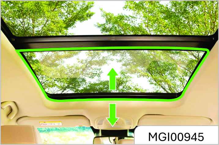
The sunroof visor can only be opened and closed manually.
Panoramic Sunroof*
The panoramic sunroof is composed of two parts—the front part is tiltable and slidable and the rear part is fixed.
Sun Blind
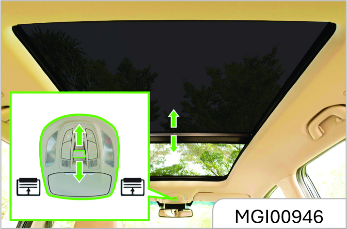
Press the open or close button of the sun blind to slide open or close the sun blind. When it reaches the desired position, release the button.
Short press the button, and the sun blind can be opened or closed automatically.
Sunroof Tilting
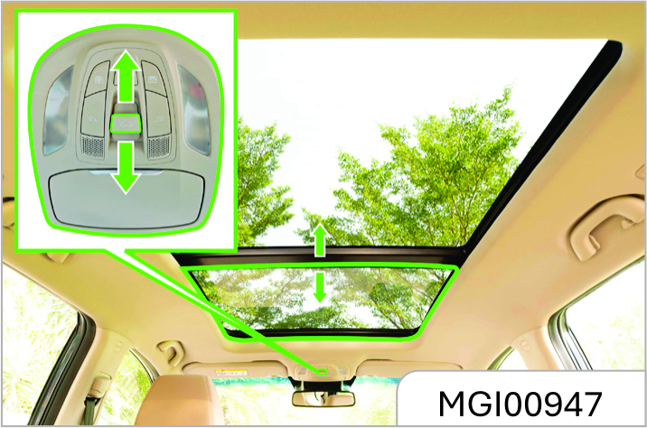
The front part of the sunroof can be tilted.
To tilt open the sunroof, push the sunroof switch backward when the sunroof is completely closed, and release the switch when the sunroof reaches the desired position. To completely tilt open the sunroof, push and hold the switch, and then release the switch when the sunroof stops moving.
You can also push the sunroof switch (short press) backward once quickly, and the sunroof will be tilted open automatically.
To close the titled sunroof, push the sunroof switch forward, and release the switch when the sunroof reaches the desired position. To completely close the sunroof, release the switch when the sunroof stops moving. You can also push the sunroof switch (short press) forward once quickly, and the sunroof will be closed automatically.
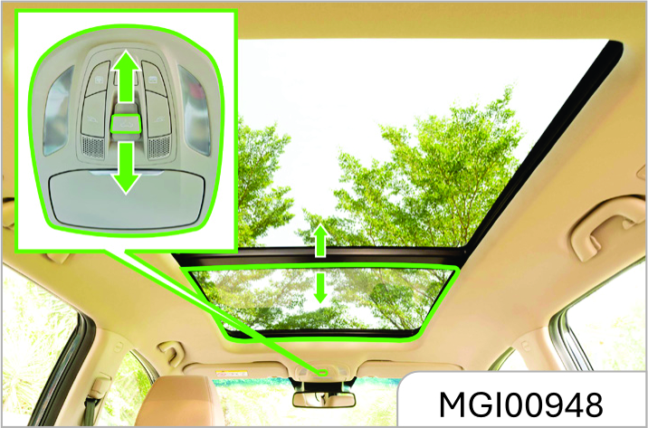
Sunroof Sliding
The sunroof can be slided open backward after it is completely tilted open.
To slide open the sunroof, push the sunroof switch backward, and release the switch when the sunroof reaches the desired position. You can also push the sunroof switch backward once quickly (short press), and the sunroof will be slided open automatically
To slide close the sunroof, push the sunroof switch forward, and release the switch when the sunroof reaches the desired position. To completely close the sunroof, release the switch when the sunroof stops moving. You can also push the sunroof switch forward once quickly (short press), and the sunroof will be slided close automatically.
One-button Opening or Closing
Push the switch once quickly (short press) while operating the sunroof switch, and the sunroof can be closed or opened automatically. In the process of opening, push the switch backward once quickly (short press) to tilt open the sunroof; push again to slide open the sunroof.
In the process of closing, push the switch forward once quickly (short press), and the sunroof will be completely closed automatically.
To stop in the process of automatic opening or closing, push the switch once.
Anti-pinch Function
The sunroof and the sun blind will retract to reduce pinching risks when they contact a certain rigid obstacle (such as the arm and head) in their one-button closing or remote closing process.
Remote Sunroof Opening
Press the unlock button of the remote control for about 2s, the sun blind and sunroof will completely be opened automatically.
Sunroof Initialization Learning
The sunroof or the sun blind may lose its onebutton opening or closing function in some cases, such as replacement of sunroof glass or motor. In such cases, the sunroof or sun blind initialization learning is necessary.
Method:
Move the sunroof or sun blind to the completely close position, push the sunroof switch forward for about 10s or press the close button of the sun blind for about 10s, when the operation sound of the sunroof mechanism is heard, the sunroof or sun blind initialization learning is completed. If the onebutton opening or closing function still cannot be recovered after initialization learning, please drive to the JSW MG Authorised Service Center for check and repair.
Shutdown Delay Function
Within 30s upon vehicle shutdown, the sunroof and sun blind can be closed with buttons but cannot be opened.
Linkage Function
The linkage function of the sunroof and sun blind enables passengers in the vehicle to see the sunroof glass position when the sunroof is opened and to avoid forgetting to close the sunroof when the passengers leave the vehicle.
When the sunroof sun blind is completed closed, the sun blind will move the half-open position along with the sunroof if the sunroof switch is pushed backward and held. If the button is released in the long pressing process, the glass will stop moving immediately, and the sun blind will move to the half-open position and then stop.
When the sunroof glass is completely opened, if the sun blind close button is long pressed, the glass will be closed along with the sun blind. If the button is released in long pressing process, the glass will stop moving, and the sun blind will stop moving (not reaching the half open position) or return to the halfopen position (exceeding the half-open position).
3.4 Instrument Pannel
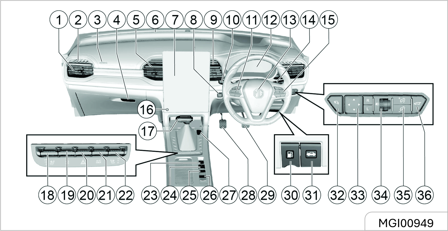
- Front passanger air vent
- Front window defroster vent
- Front passenger airbag
- Glove box
- Central air vent
- Front air outlet
- Infotainment System
- Ignition switch
- Central air vent
- Wiper and washer switch
- Fixed speed cruise control button
- Instrument Cluster
- Driver airbag / horn switch
- Headlights, turn signal switches
- Sound system control button
- Infotainment System button
- Gear Knob
- Air Volume Decrease Key
- ESC OFF switch
- Hazard warning light switch
- A/C MAX switch
- Air Volume Increase Key
- Electronic hand brake switch
- Start and stop system switch
- Parking assist system switch
- Spare key
- Economic mode switch
- Brake pedal
- Accelerator pedal
- Fuel filler cap release handle
- Hood release lever
- ORVM folding switch
- Electrically operated ORVM adjustment switch
- Headlight beam adjustment regulator
- Instrument Cluster brightness adjustment switch
- Tailgate opening switch
3.4.1 Controls
Horn
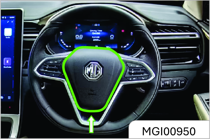
Press the switch on the steering wheel to blow the horn.
Steering Wheel Adjustment*
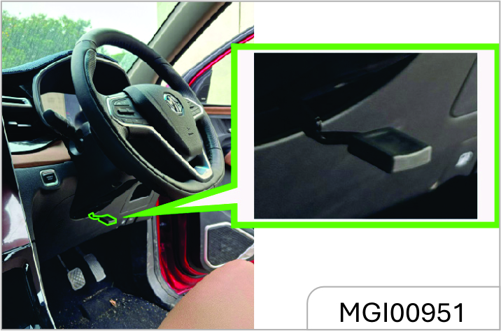
It is only allowed to adjust the steering wheel after the vehicle has fully stopped. The steering wheel can tilt up / down and towards / away.
If you need to adjust the steering wheel:
- As is shown in the figure, push the steering wheel adjustment lever downward first.
- Adjust the steering wheel to the desired position (either down and away or down and toward you) and then pull back the adjustment lever to lock the steering wheel.
- Check and confirm that the steering wheel has been locked firmly.
The driver must keep absolute control of the steering wheel during driving.
It is not allowed to adjust the steering wheel while the vehicle is running. Adjusting the steering wheel during driving can cause the vehicle out of control.
Front Windshield Wiper and Washer*
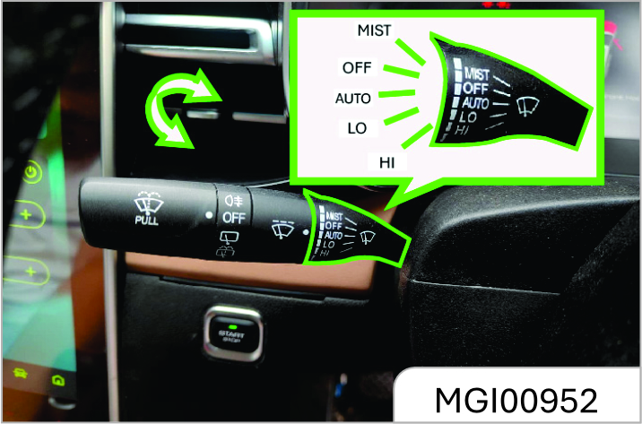
To use the front windshield wiper, turn on the ignition switch first and then push the windshield wiper / washer control lever. The front windshield wiper has the following 5 working positions:
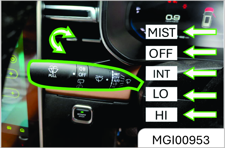
MIST: Push the control lever up once and the wiper wipes once.
OFF: Turn the system off.
AUTO*: This feature senses rain or snow fall on the windshield and automatically activates the wipers for the driver.
LO: Push the control lever down to this position and the wiper wipes continuously at a low speed.
HI: Push the control lever down to this position and the wiper wipes continuously at a high speed.
INT*: This feature sweeps the windscreen at regular intervals as configured.
The intermittent and automatic wiping speed is adjustable and to select the desired speed, just turn the circular knob in the middle of the control lever.
Front Windshield Washer
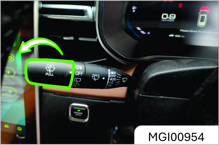
To spray cleaning fluid on the front windshield:
- Turn the ignition switch to "ON (Connected)" position.
- Pull the windshield wiper/washer control lever towards the steering wheel.
Keep pulling the control lever for more than 1s or so—the washer sprays cleaning fluid to the windshield and works for 3 cycles or until the control lever is released.
- Blurred view for the driver can lead to accident and cause personal injuries and damage to the vehicle or other properties.
- In cold weather, if the wiper gets frozen, before using the wiper, please spray warm water on the frozen area to device and then wipe off the water immediately to prevent icing.
Rear Windshield Wiper and Washer*
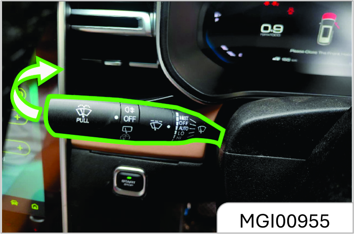
To use the rear windshield washer, turn the ignition switch to "ON" position first and then turn the rear wiper and washer switch knob too.
Turn the rear wiper and washer switch knob to and the water pump sprays water to the rear windshield immediately. Release the knob and the pump stops spraying.
Exterior Entertainment Power Outlet*
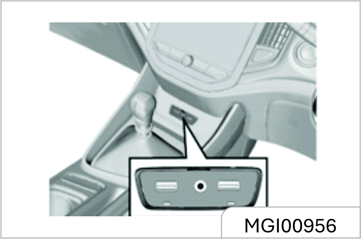
The entertainment system interface is located below the air conditioning panel. USB interface specification is 5V/2A, can be connected to play audio, charging.
Power will not be available for charging when the vehicle ignition switch is off.
Exterior Entertainment Power Outlet* (LV3/LV4)
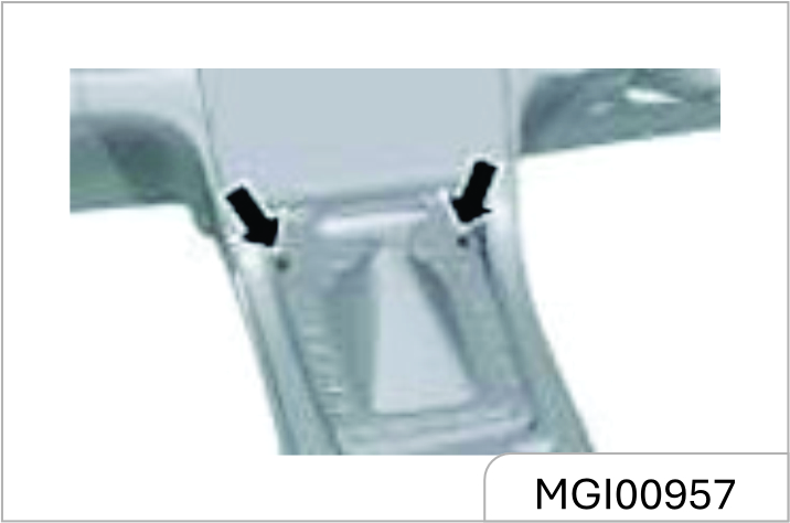
Rear Accessory USB Power Outlet*
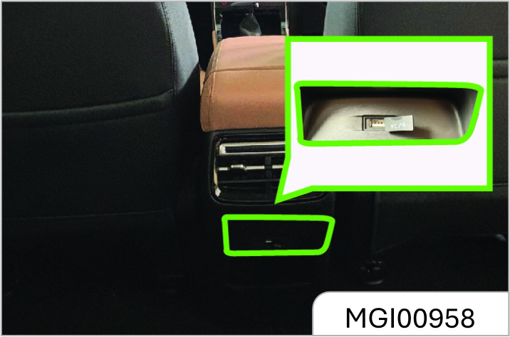
The second-row USB power outlet (5V/2A) is located at the rear end of the console and it can be used for cell phone charging. The power outlet is unavailable if the ignition switch is turned off.
If equipped, the third-row USB power outlet is located at the third-row seat right armrest.
Rear Power USB Port *
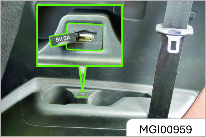
There is USB power jacks (5V/2A) available for the second and third row seat and can be used for charging mobile phones. The power is not available when the vehicle ignition switch is off.
Wireless Charging System for Mobile Phones *
The wireless charging function for a mobile phone is realized without the necessity for a connection cable. It is achieved using electromagnetic induction.
The wireless charging function does not apply to all mobile phones, only brands/models with wireless charging function.
The wireless charging function for a mobile phone is realized without the necessity for a connection cable. It is achieved using electromagnetic induction.
Wireless Charger in the car can be used to charge Qi certified mobile phones wirelessly.
Mobile phone (Receiver) controls the power transfer from the Wireless charger in the Car (Transmitter). So, Charging rate of the phone will vary based on type/brand of phone used.
The wireless charging function does not apply to all mobile phones, only brands/models with wireless charging function.
For using a mobile phone without wireless charging function, need to use Qi certified accessories / adapter.
Wireless Charging of Mobile Phones The wireless charging area is located in the area shown in the figure. The charging function is enabled when the START/ STOP Switch is placed in the ACC/ ON/ READY positions. All doors should be closed.
Place the phone face up horizontally in the charging area, which can be used for wireless charging.
Only one mobile phone can be charged at a time.
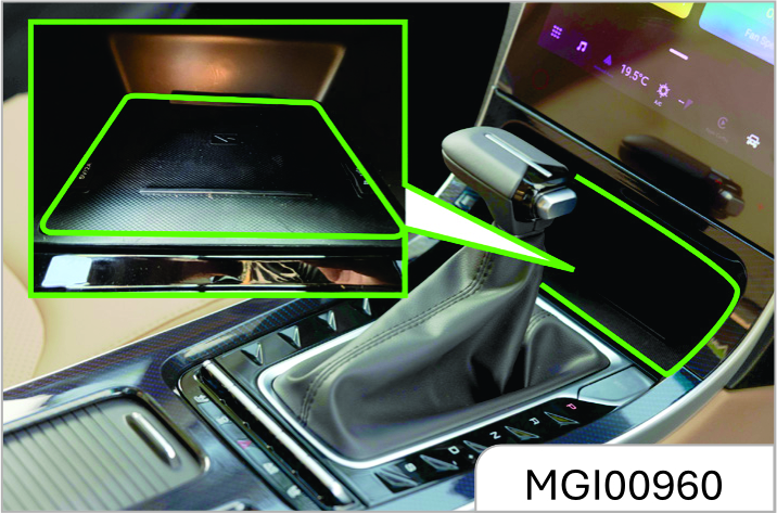
Ensure that phone is kept properly on the charging pad. There is possibility of inadequate charging if the mobile phone is not resting properly on the charging pad, in such conditions the phone should be lifted and placed back properly.
Do not keep any metal object in the Charging Pad along with Mobile Phone. It will affect phone charging performance. Also, it may cause overheating of phone and metal objects.
Smart phones of some manufacturers may display charging indication on weak current and no increase in net charge. This is due to the particular characteristic of the smart phone and does not imply a malfunction on wireless charging function.
For certain mobile phones with their own protection, the wireless charging speed may decrease sometimes, and the wireless charging may stop.
The wireless charging efficiency may reduce when there is a heavy accessory cover on the smart phone.
Items like vehicle Keys ,Pen, Coins, Magnetic components such as credit card, telephone card, bankbook, any transportation ticket or any metallic objects should not be kept on Wireless charging pad /over mobile phone while charging. They may get damaged and may also affect mobile charging performance. When any smart phone without a wireless charging function is placed on the charging pad ,It does not affect the vehicle or the smart phone in any way.
On bumpy roads, the wireless charging function of the mobile phone may intermittently stop and resume. If the mobile phone deviates from the charging area and stops charging, it will need to be placed back in the rechargeable area.
The size of each brand of mobile phone is different, and the position of the charging coil on the mobile phone is different. Please adjust the position of the mobile phone accordingly. In addition, the case of some mobile phones may have an impact on wireless charging. It may be necessary to adjust or remove the case to achieve wireless charging.
If the mobile phone cannot be charged correctly, please make sure that there is no foreign matter in the wireless charging area or wait for the wireless charging area to cool down before further attempts. If it still fails, seek an JSW MG Authorised Dealership.
"The wireless cellular phone charging system may not support certain cellular phones, which are not verified for QI specification"
Few wirelless charger cellular phone have limited charging performance, and this is due to inbuilt protection added by phone manufacturers.
Eg. Latest iphone models have inbuilt Mag safe technology which limits the wireless charging performance.
When the wireless charging system of the mobile phone is being used, make sure that the smart key is 20cm or more away from the wireless charging area.
Do not place coins, IC cards, metal keys, or other items with a large amount of metal composition in the wireless charging area with your phone. This may result in the failure of wireless charging function and create a safety hazard.
3.4.2 Instrument Cluster
Speedometer
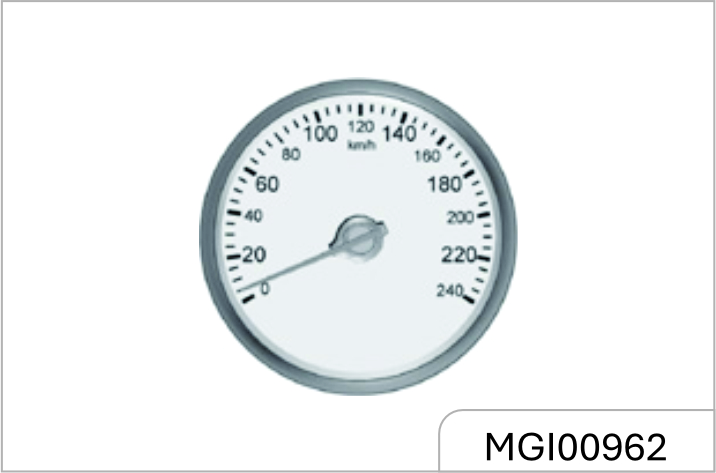
It displays the vehicle speed.
Please keep the speed within the limit when driving in a speed limit zone.
Tachometer
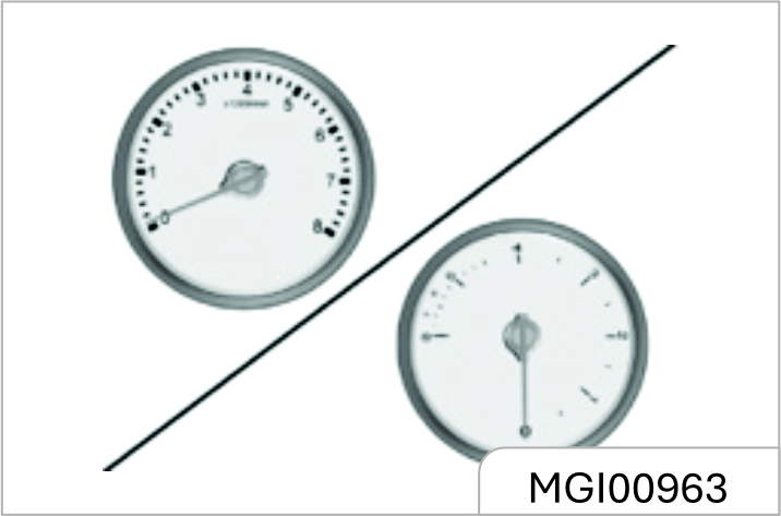
It displays the engine crankshaft revolutions per minute.
Fuel Gauge
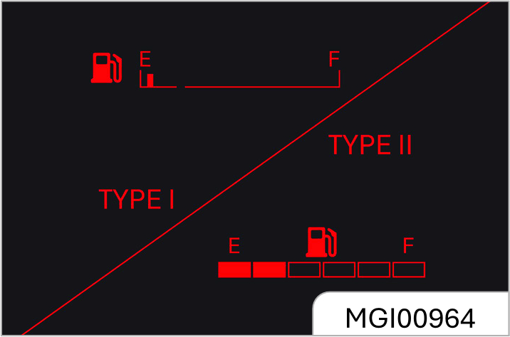
It displays the fuel level in the fuel tank.
If the fuel level in the fuel tank is too low, the control indicator will illuminate. Please add fuel immediately. It is strictly prohibited to use up the fuel in the fuel tank.
As some fuel remains in the fuel tank, the adding amount can be less than the fuel tank capacity. During braking, acceleration or cornering, as the fuel in the fuel tank shakes, indication on the fuel gauge fluctuates.
Before adding fuel, please do stop the vehicle and shut down the engine.
General Odometer
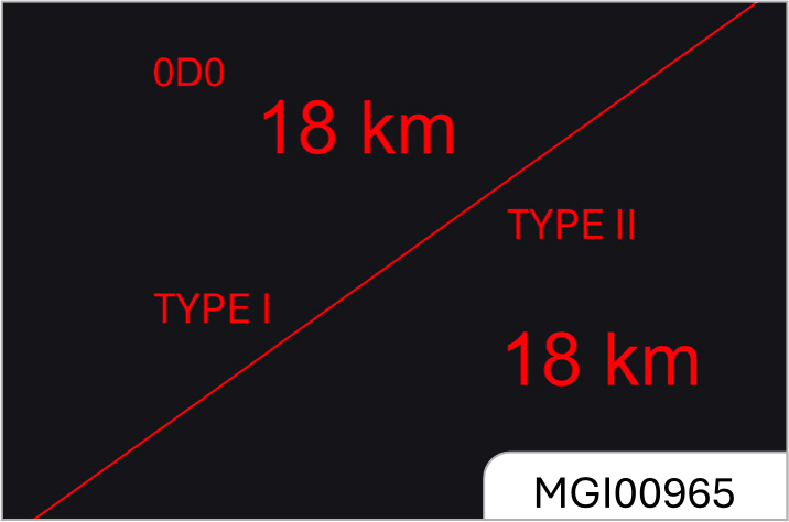
It shows vehicle kilometers for a driving trip After it has been reset to zero. In this mode, long press the adjustment lever to clear the trip distance.
You can clear the trip distance when it is displayed on the small odometer. To do this, long press "OK" button on the steering wheel if the vehicle is of high configuration; long press the instrument cluster adjustment lever if the vehicle is of low configuration.
If the engine coolant temperature is too high, please stop the vehicle, shut down the engine and inspect the coolant level.
Type-1 Trip Computer Display Screen
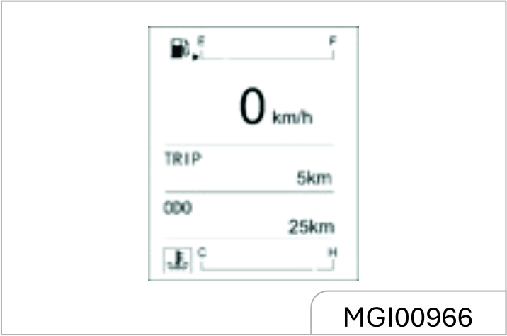
The trip computer monitor is located between the tachometer and the speedometer. It can display fuel gauge, engine coolant temperature gauge, general odometer, small odometer, fuel range, depending on the vehicle configuration.
Adjustment Lever
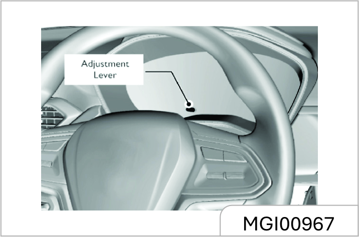
Short press or long press the adjustment lever to switch among different screens or carry out zeroing.
Long press means press for over 2s and short press means press for 2s or less.
Rotate the adjustment lever to adjust the display brightness of the instrument cluster.
For more details, please refer to "Display Screen Mode Switch".
Type - 1 Trip Computer Display Screen Switch
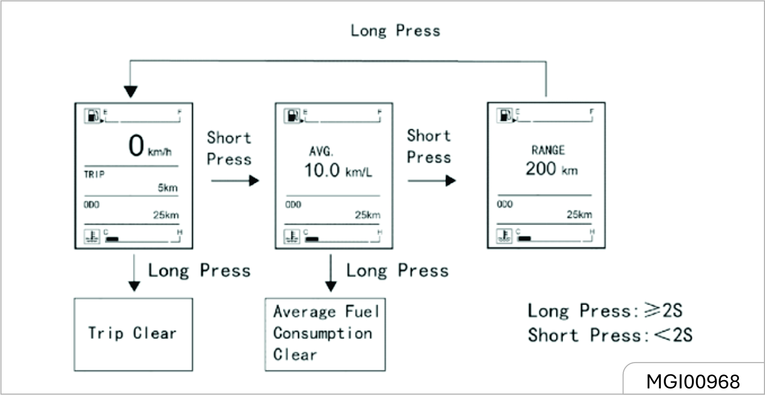
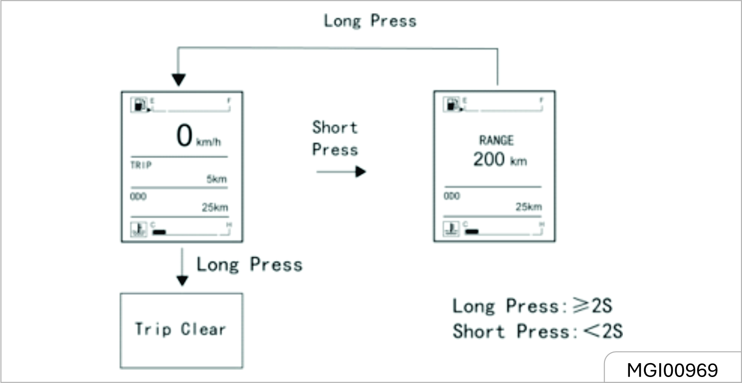
Type-2 Trip Computer Display Screen
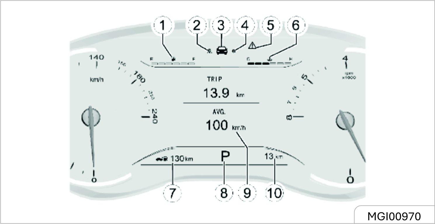
- Fuel Level
- Navigation Information Display Option
- Vehicle Information Setup Option
- Settings
- Warnings
- Coolant Temperature
- Distance To Empty (Range)
- Gear Position Display* (equipped on AT model only)
- Display Zone
- General Odometer
Instrument Cluster Control Button*
Type-II trip computer display screen can be controlled with the control button on the steering wheel. Only when the ignition switch is turned to ON can the instrument cluster be controlled.
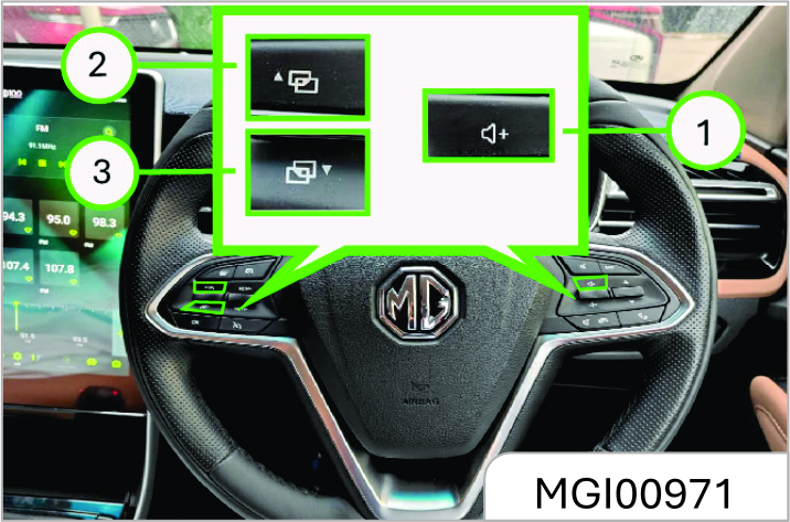
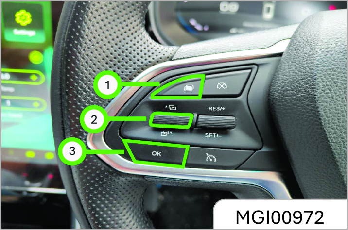
-
Option switch button
It is used to switch among different display screens.
-
Up/down selection button
Pull it up or down to make selection or adjustment.
-
Confirm button (OK)
It is used to confirm the setup or to clear the trip mileage. The confirm button can be operated in two ways: short press (<2S) and long press (<2S).
Trip Computer Information Option
Choose this option to indicate driving information such as odometer, current vehicle speed, driving time, fuel range, tyre pressure, etc. Pull the up/down selection button to switch among the following interfaces:
Interface - 1
Trip / Average Speed
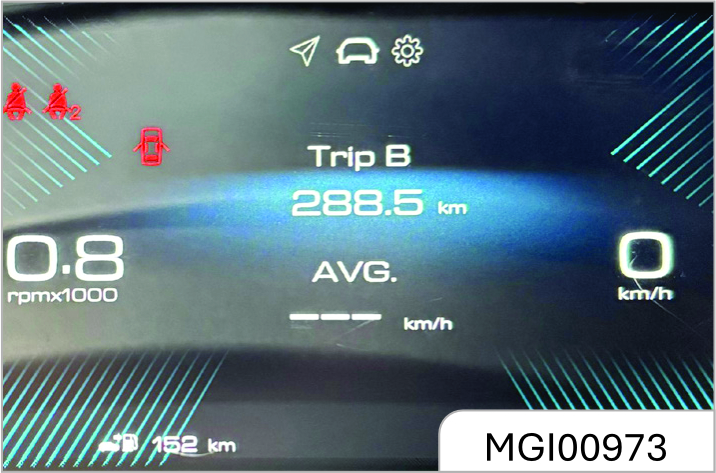
The first trip mileage within the recent driving distance is shown.
Interface - 2
Tyre Pressure Indication
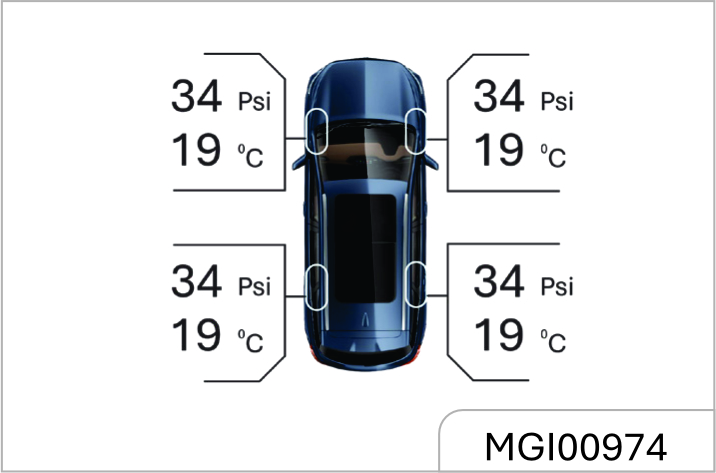
The Tyre Pressure Monitor System (TPMS) displays the current pressure and temperature of the four tyres respectively.
When the system detects tyre pressure low or high, it gives a prompt, asking you to adjust the tyre pressure in time. For the standard tyre pressures, please refer to "Technical Data"
If the tyre temperature value becomes extremely great, for example, when you are driving down a slope and applies the brake frequently, please stop the vehicle to cool down the tyres. If the shown tyre temperature value becomes abnormal, please contact the JSW MG Authorized Service center as soon as possible for inspection and repair.
Please keep the tyre pressure within the reference range, otherwise the tyre service life and vehicle controllability can be reduced, or flat tyre can happen which is very dangerous. Please do not continue driving if the tyre temperature is extremely high. Once overheated, the brake may fail to provide sufficient braking force and the tyre may become flat. Please stop the vehicle as soon as possible to cool down the tyre and carry out inspection.
Interface - 3
Driving Time / Fuel Range
Calculation of the driving time starts as the vehicle starts running and ends as the vehicle stops. The indication can be 23 hours plus 59 minutes at maximum.
After the driving time reaches the maximum record value, or when the battery gets disconnected, or the engine flameout condition lasts for 2 hours, the driving time will clear automatically and calculation starts as new.
The displayed fuel range is calculated based on the current fuel consumption and the fuel amount left in the fuel tank. It changes as the driving condition changes. When the fuel level low warning indicator illuminates, "fuel insufficient, add fuel" will appear in the fuel range indication area. If you long press "OK" on the current interface, the driving time will be cleared, while the fuel range cannot be cleared.
Vehicle Information Setup Option
This option allows access to fault information inquiry, overspeed warning setup, fatigue driving setup and display language setup.
Pull the up/down selection button and then press "0K" to enter the interface under this option.
The control button on the steering wheel will be shielded as a warning message pops out on the display screen. The control button will give no response even though it is pressed until the warning message disappears.
Interface -1
Fault Information Inquiry
Press "OK" and you will enter the fault information inquiry interface. If no fault information is shown, a prompt saying no fault information exists will appear on the LCD, if any fault information is shown, you can check it one by one by pushing the up/down selection button.
Press "OK" to return to the parent directory.
If any fault exists at the time of vehicle start, a fault warning will appear and last for 5s. Please contact the Service Center for inspection and repair.
When the icon under this option changes to what is shown above, it indicates a vehicle fault to which you should keep alert. Please contact the JSW MG Authorized Service center in time for inspection and repair to eliminate the safety hazard.
Interface – 2
Fatigue Driving Warning Setup
Enter the fatigue driving function setup interface and you can make fatigue driving function setup. Once the driving time reaches or exceeds the set value, a text warning message will appear on the LCD, accompanied by a sound alarm. The system reminds you to have a rest if necessary in this way. You can also disable the fatigue driving function by selecting the corresponding option on this interface. The fatigue driving function gets disabled by fault once the battery power is cut off.
Set range of fatigue driving warning: 1h~ 4h at an increment/decrement of 0.5h.
Multimedia Information Option
Choose this option and the instrument cluster will show AM, FM or audio information real- time on the screen. If the instrument cluster has not connected to the relevant system, "Connecting Multimedia" will appear on the screen.
Bluetooth Telephone Information Option
Choose this option and the Bluetooth telephone interface will appear. If the instrument cluster has not connected to Bluetooth telephone, "Telephone Not Connected" will appear on the screen. After successfull connection, "Telephone Connected" will appear on the screen.
The instrument cluster will show the current state of Bluetooth telephone on the screen: "incoming call", "outgoing call" and "on the line".
In addition, the instrument cluster will also show the current telephone number and name of the contact on the screen.
Navigation Information Option
Choose this option and the instrument cluster will show "road name", "destination" "distance information" or indication icon on the screen, depending on the current state of the navigation system.
If the instrument cluster has not connected to the navigation system, "Connecting Navigation" will appear on the screen.
Gear Position Display* (Equipped On AT Model Only)

The automatic transmission has two control types: manual and automatic, displayed as "M" and "A" respectively.
Gear position display prompt includes two parts: mode prompt and gear position prompt. In automatic (A) mode, two transmission control modes are available: economy and sports, displayed as "E" and "S" respectively.
In automatic (A) mode, three gear positions will be displayed: D, R and N.
In manual (M) mode, the following gear positions will be displayed: 1, 2, 3, 4, 5, 6 (if equipped), R and N. When driving in this mode, you will be reminded to shift up as the vehicle speed reaches certain value and at the same time, the arrow icon in the gear position display area will illuminate.
For more details, please refer to "Automatic Transmission" in the driving and control section.
Door Ajar Warning Lamp
If any door in the front or rear row is ajar or not fully closed, a warning lamp shaped like the door ajar will illuminate, if the liftgate is ajar or not fully closed, a warning lamp shaped like a liftgate ajar will illuminate or flash.
If any door is not fully closed while the vehicle is running at a speed of 10 km/h, a door ajar alarm sound will be issued.
Instrument Cluster Display Brightness Adjustment
Type - I Instrument Cluster*
Turn the adjustment lever to set the desired display brightness. After adjustment, if no operation is conducted within 2s, the system will turn back to the previous interface.
Type - I Instrument Cluster
If the vehicle is equipped with a Type-I trip computer display screen, you can short press or long press the adjustment lever on the instrument cluster to switch the display modes or conduct clearing. As it is shown in the figure:
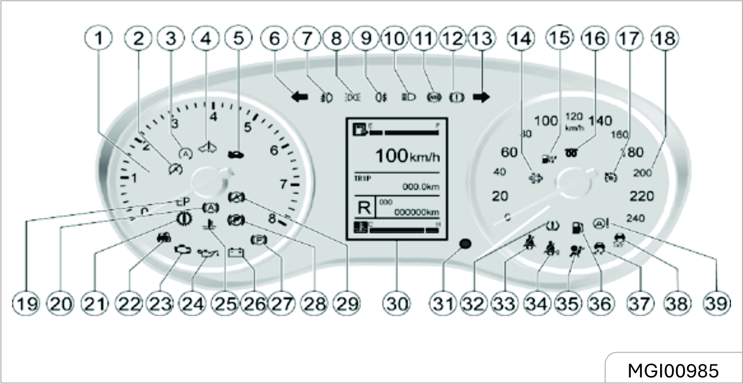
- Engine Tachometer
- Start And Stop System Shutdown Indicator*
- Start And Stop System Work Indicator*
- 48v System Failure Warning Light*
- Engine Compar tment Opening Indicator*
- Left Turn Signal / Hazard Warning Indicator
- Front Fog Light Indicator*
- Position Light Indicator
- Rear Fog Light Indicator
- Headlights High Beam Indicator
- Abs Failure Warning Light
- Brake System / Hand Brake Indicator / EBD Warning Light
- Right Turn Signal / Hazard Warnin Indicator
- Particle Trap Indicator Light*
- Fuel Water Indicator Light*
- Glow Plug Indicator Light*
- Fixed Speed Cruise Work Status Indicator*
- Speedometer
- Emergency Stop Light* SCR (Selective Catalytic Reduction) Warning Light
- Automatic Parking (AVH) Work Indicator*
- Transmission Fault Warning Light*
- Engine Anti-theft System Indicator / Immolizer
- Engine Failure Warning Light Mil
- Oil Pressure Is Too Low Warning Light
- Engine Water Temperature Is Too High Warning Light
- Charging System Fault Warning Light
- Electronic Hand Brake Work Indicator*
- Electronic Hand Brake Failure Warning Light*
- Automatic Parking (AVH) Fault Warning Light*
- Driving Computer Display
- Display Adjustment Lever
- Tyre Pressure Monitoring System (TPMS) Failure Warning Light*
- Driver Side Seat Belt Warning Light
- Passenger Side Seat Belts Warning Lights*
- Airbag Failure Warning Light
- Fuel Level Low Warning Light
- Electronic Stability Control (ESC) Fault Alarm Notice Light
- Electronic Stability Control (ESC) Shutdown Refers To Light
- Electronic Power Steering (EPS) Fault Warning Light
When the ignition switch is turned on, it is used as a function test.
Most control lights will be activated for a short time bright.
The Control Indicator Color Means:
Red = Dangerous, Important Reminder.
Yellow = Warning, Message, Fault.
Green = Confirm Enable.
Type - II Instrument Cluster
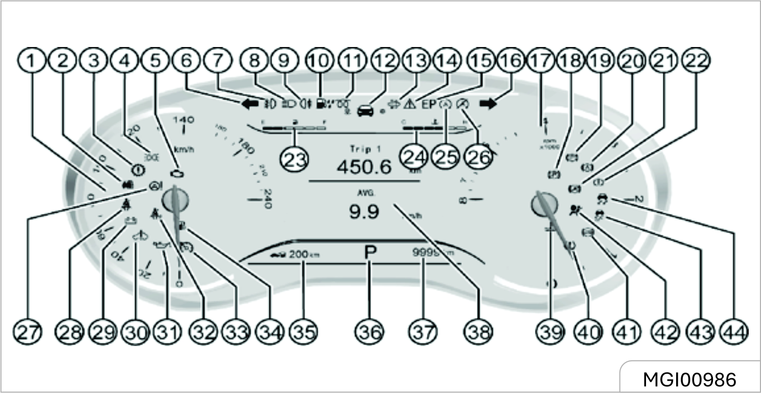
- Speedometer
- Engine anti-theft system indicator / Immobilizer
- Transmission Failure Warning Light*
- Position Light Indicator
- Engine Failure Warning Light
- Left Turn Signal / Hazard Warning Indicator
- Front Fog Light Indicator*
- Headlights High Beam Indicator
- Rear Fog Light Indicator
- Fuel Water Indicator Light*
- Glow Plug Indicator Light*
- Driving Computer Information Tab
- Particle Trap Indicator Light*
- Fault Information Prompt
- Emergency Stop Light*
- Right Turn Signal / Hazard Warning Indicator
- Engine Tachometer
- Electronic Hand Brake Failure Warning Light*
- Electronic Hand Brake Work Indicator*
- Automatic Parking (AVH) Work Indicator*
- Automatic Parking (AVH) Fault Warning Light*
- Brake System / Hand Brake Indicator / EBD Warning Light
- Fuel Gauge
- Water Temperature Gauge
- Start and Stop System Work Indicator*
- Start And Stop System Shutdown Indicator*
- Electric Power Steering (EPS) Warning Light
- Driver side Seat Belt Warning Light
- Charging System Failure Warning Light
- 48v System Failure Warning Light*
- Low Oil Pressure Warning Light
- Passenger side Seat Belts Warning Lights
- Constant Speed Cruise Work Status Indicator*
- Fuel Level Low Warning Light
- Distance to empty (Fuel range) SCR (Selective Catalytic Reduction) Warning Light
- Gear Display*
- Total Odometer
- Display
- Water Temperature Warning Lamp
- Tyre Pressure Monitoring System (TPMS) Fault Indication light*
- ABS Warning Light
- Airbag Failure Warning Light
- Electronic Stability Control (ESC) shutdown refers to Light*
- Electronic Stability Control (ESC) Fault Alarm Notice light*
When the ignition switch is turned on, it is used as a function test.
Try, most control lights will be activated for a short time bright.
Control indicator color one position:
Red = dangerous, important reminder.
Yellow = warning, message, fault.
Green = Confirm Enable. Blue = Confirm Enable.
Type - III Instrument Cluster
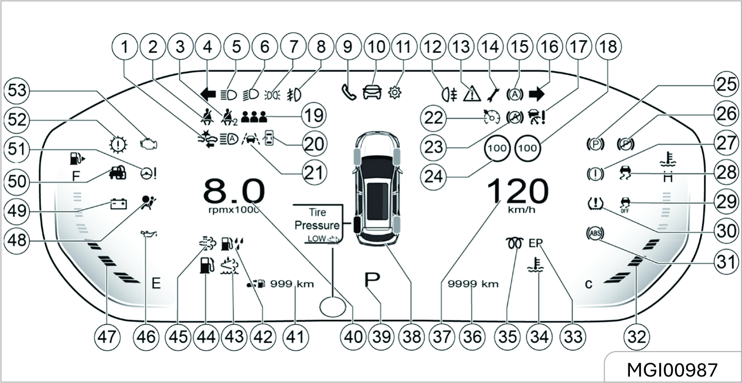
- Forward Collision Warning and Automatic Emergency Brake Warning Light*
- Driver side Seat Belt Warning Light
- Passenger side Seat Belts Warning Lights
- Left Turn Signal / Hazard Warning Indicator
- Headlights High Beam Indicator
- Headlights Low Beam Indicator
- Position Light Indicator
- Front Fog Light Indicator
- Bluetooth Telephone Information Display Option*
- Driving Computer Information Tab
- Vehicle Information Setup Option
- Rear Fog Light Indicator
- Fault Information Prompt
- Maintenance Reminder
- Start and Stop System Work Indicator
- Right Turn Signal / Hazard Warning Indicator
- Cruise Control Failure Warning Light
- Adaptive Cruise Control Speed*
- Rear Passenger Belt Warning Light
- Door Ajar Warming Lamp
- Lane Keeping Assist Work Indicator
- Constant Speed Cruise Work Status Indicator
- Start And Stop System Shutdown Indicator
- Cruise Control Speed
- Electronic Hand Brake Work Indicator
- Electronic Hand Brake Failure Warning Light
- Brake System / Hand Brake Indicator / EBD Warning Light
- Electronic Stability Control (ESC) Fault Alarm Notice light
- Electronic Stability Control (ESC) Off Light
- Tyre Pressure Monitoring System (TPMS) Fault Indication light
- ABS Warning Light
- Coolant Temperature Gauge
- Emergency Stop Light
- Engine Water Temperature Is Too High Warning Light
- Glow Plug Indicator Light
- Total Odometer
- Display
- Tyre Pressure Monitoring System (TPMS) Fault Indication light
- Gear Display
- Engine Tachometer
- Distance to empty (Fuel range)
- Fuel Water Indicator Light
- SCR (Selective Catalytic Reduction) Warning Light
- Fuel Level Low Warning Light
- Particle Trap Indicator Light
- Low Oil Pressure Warning Light
- Oil Gauge
- Airbag Failure Warning Light
- Charging System Failure Warning Light
- Engine anti-theft systemindicator/ Immobilizer
- Electric Power Steering (EPS) Warning Light
- Transmission Failure Warning Light
- Engine Failure Warning Light
When the ignition switch is turned on, it is used as a function test.Try, most control lights will be activated for a short time bright.
Control indicator color one position:
Red = dangerous, important reminder.
Yellow = warning, message, fault.
Green = Confirm Enable. Blue = Confirm Enable.
3.5 Warning Lights & Indicators
Turn Signal Lamp / Hazard Warning Indicator

The turn signal lamp / hazard warning lamp indicator is used to confirm whether the outside turn signal lamp / hazard flasher can work normally. If you find that the green arrow does not flash as you send a turning signal or press the hazard warning button, please inspect the fuse and bulb and if necessary, replace them.
These indicators are essential for assurance of driving safety. If the turn signal lamp or the hazard flasher indicator bulb has burnt out, please replace it immediately. If you fail to keep these indicators in an agreeable working condition, accident may happen and as a result, personal injuries, and damage to the vehicle or other properties can occur.
If the flashing time is shorter than normal, it indicates that the turn signal lamp bulb has burnt out and must be replaced.
Engine Oil Pressure Too Low Warning Lamp
As you turn on the ignition switch, the engine oil pressure too low warning lamp illuminates and it goes out after the engine gets started. This indicates that the indicator bulb can work normally.
If this warning lamp illuminates while the engine is running, it indicates that the engine oil pressure may have dropped to a dangerous level. Please stop the engine and check the oil level immediately.
If the oil level is too low, please add the specified engine oil to the appropriate level. Please refer to the information about engine oil level check provided in "Vehicle Maintenance". If the oil level is normal, please go to the nearest JSW MG Authorised Service Center to check the lubrication system.
When the engine oil pressure too low warning lamp illuminates, it indicates that the engine oil pressure may have dropped to a dangerous level. Please do not drive the vehicle when the warning lamp has illuminated. Otherwise, the repair charge will be expensive.
Charging System Warning Lamp

This warning lamp illuminates as you turn on the ignition switch. It goes out as the engine gets started. If the charging system warning lamp illuminates during driving:
Drive the vehicle off the lane in a safe manner.
- Stop the vehicle.
- Check and confirm that the drive belt has not loosened or broken.
- If the drive belt is normal but the charging system warning lamp keeps illuminated, it can indicate a charging system fault. We advise you to go to the nearest JSW MG Authorised Service Centre for vehicle repair as soon as possible.
If the charging system warning lamp illuminates, it may indicate a charging system fault.
Please do not drive the vehicle when the charging system warning lamp has illuminated, otherwise the vehicle can be damaged.
If you often drive the vehicle for short trips, the battery capacity consumes more quickly, so it is necessary to replenish the electric energy by charging the battery or having a long trip.
Coolant Temperature Too High Warning Lamp

This warning lamp illuminates as you turn on the ignition switch and it goes out several seconds later. It indicates that both the system and the indicator bulb can work normally.
This indicator illuminates when the coolant temperature becomes excessively high. It indicates that the engine has over heated. Please do not continue driving the vehicle.
Front Fog Lamp Indicator*

This indicator illuminates when the front fog lamp is turned on. Refer to "Front Fog Lamp" in the lighting section.
Rear Fog Lamp Indicator

This indicator illuminates when the rear fog lamp is turned on. Refer to "Rear Fog Lamp" in the lighting section.
Headlamp High Beam Indicator

The high beam indicator illuminates when the headlamp high beam is turned on.
Position Lamp Indicator

This indicator illuminates when the position lamp is turned on.
Engine Malfunction Indicator Lamp (MIL)

This indicator lamp illuminates when the ignition switch is turned on but the engine has not started. This indicates that the indicator lamp bulb can work normally. The lamp goes out after the engine is started. This malfunction indicator lamp (MIL) illuminates upon occurrence of any component or subsystem fault related to the emission system. Once the electronic control module (ECM) detects any fault, the malfunction indicator lamp will keep illuminated. In case that serious misfire is detected, the malfunction indicator lamp will flash constantly. Serious misfire can cause damage to the catalytic converter. In case of this, the electronic system of the vehicle will switch to an emergency running
procedure so that you can continue the trip. However, we advise you to go to the nearest JSW MG Authorised Service Center for fault removal as soon as possible. If MIL illuminates for a while and then goes out, it is normal, not indicating any system fault.
If MIL illuminates, it indicates a fault that must be noted. Continuous driving after MIL has illuminated can cause damage to the emission control system, and reduce fuel economy and vehicle controllability. We advise you to go to the nearest JSW MG Authorised Service Center for vehicle repair as soon as possible.
ABS Fault Warning Lamp

The ABS warning lamp will illuminate immediately the ignition switch is turned on. It indicates that the system is conducting Self-inspection and the warning lamp bulb can work normally. The warning lamp goes out several seconds later.
When the ABS warning lamp gets into the following states, please consult the nearest JSW MG Authorised Service Center.
- Not illuminated as the ignition switch is turned on
- Always illuminated
- Illuminated during driving
If the ABS warning lamp illuminates during driving, it indicates possibility of an ABS fault. Though the vehicle can run normally without ABS function, but we strongly advise you to go to the nearest JSW MG Authorized Service Center for ABS inspection and necessary repair.
Illuminated ABS warning lamp can also indicate that the brake cannot work normally. If you fail to keep the brake in an agreeable working condition, collision may happen and as a result, personal injuries, and damage to the vehicle or other properties can occur.
EPS Fault Warning Lamp

This warning lamp will illuminate immediately the ignition switch is turned on. It indicates that the system is conducting self-inspection and the warning lamp bulb can work normally. The warning lamp goes out several seconds later.
When the electronic power steering (EPS) system detects a fault, the warning lamp will give out an indication. The vehicle can still steer even the steering system has a fault, but it demands much greater effort. In case of the following circumstances, please consult the nearest JSW MG Authorised Service Center.
- The lamp does not illuminate when the ignition switch is turned on.
- The lamp does not go out after it illuminates.
- The lamp Illuminates during driving.
Illuminated ABS warning lamp can indicate that the electronic power steering column cannot work normally. If you fail to keep the steering column in an agreeable working condition, collision may happen and as a result, personal injuries, and damage to the vehicle or other properties can occur.
Airbag Fault Warning Lamp

The airbag warning lamp illuminates when the ignition switch is turned on and it goes out several seconds later.
This indicates that both the warning lamp bulb and the airbag system can work normally.
In case of an airbag fault, the warning lamp will give out indication in any of the following ways:
- The lamp does not illuminate when the ignition switch is turned on.
- The lamp does not go out after it illuminates.
- Flashing or keeping illuminated during driving
If the airbag warning lamp flashes or keeps illuminated during driving, it indicates an airbag system fault. The airbag system will get deactivated and thus fail to trigger off in case of an accident. We strongly advise you to drive the vehicle to the nearest JSW MG Authorised Service Center for inspection. If an accident happens after the airbag system fault has occurred, personal injuries or even death can appear as a result.
Brake System / EBD Warning Lamp

Model with Mechanical Hand Brake
The brake system warning lamp illuminates after the ignition switch is turned on and it goes out several seconds later (if the parking brake has been released). This indicates that the warning lamp can work normally.
The brake system/EBD warning lamp also illuminates when the parking brake engages. The lamp goes out after the parking brake is released. Please do fully release the parking brake before starting the vehicle.
If the brake system warning lamp illuminates after the parking brake is fully released, it indicates possibility that the brake fluid level in the fluid reservoir is too low or an EBD system fault has occurred.
In case of this, please operate in the following steps:
- Carefully drive the vehicle off the lane and then stop the vehicle.
- Check the brake fluid level.
- Add the recommended brake fluid until the fluid level reaches MAX (highest) mark. Refer to "Adding Brake/Clutc Fluid".
- In case of the following
circumstances, we advise you to
drive the vehicle at a safe speed
to the nearest JSW MG Authorised
Service Centre to inspect the brake
and confirm that:
- The brake can work normally.
- You think the brake system is safe at your own judgment.
- In case of the following
circumstances, we advise you to
tow the vehicle to the nearest JSW
MG Authorised Service Centre for
inspection and repair:
- You discovered brake system leakage.
- The brake system warning lamp keeps illuminated.
- The brake cannot work normally
Please do not drive the vehicle when the brake system warning lamp has illuminated. This phenomenon indicates possibility of brake failure to work normally. Driving the vehicle after a brake fault has occurred can lead to collision, causing personal injuries and damage to the vehicle or other properties as a result.
The brake system warning lamp illuminates after the ignition switch is turned on and it goes out several seconds later. This indicates that the warning lamp can work normally
If the brake system warning lamp keeps illuminated or illuminates during driving, it indicates possibility that the brake fluid level in the fluid reservoir is too low, or an EBD system fault has occurred. In case of this, the operation steps are the same as those for model with mechanical hand brake.
If the brake system warning lamp does not illuminate after the parking brake engages with the ignition switch turned on, please do not drive the vehicle.
Please ensure that light-emitting diode of the warning lamp works normally. If the lamp does not illuminate when the parking brake engages with the ignition switch turned on, even though light- emitting diode of the warning lamp works normally, we still advise you to go to the nearest JSW MG Authorised Service Centre to inspect the brake system.
These phenomena indicate possibility of a brake system fault. If you fail to keep the brake in an agreeable working condition, collision may happen and as a result, personal injuries, and damage to the
Engine Immobilizer System Indicator
This indicator illuminates when the door is opened. It goes out after the engine starts. This indicates that the indicator can work normally. Refer to information on engine immobilizer system given in "Driving and Controls".
Driver Fasten-Seat-Belt Warning Lamp

The seat belt warning lamp illuminates if the driver does not fasten the seat belt properly after the ignition switch is turned on. Following this, the following circumstances will appear unless the driver fastens the seat belt properly:
- The seat belt warning lamp keeps illuminated
- If the vehicle speed exceeds 20 km/h, the warning lamp will flash and the warning buzzer will buzz for a certain time.
Front Passenger Fasten-Seat-Belt Warning Lamp*

The seat belt warning lamp illuminates if the front passenger seat is occupied but the occupant does not fasten the seat belt properly after the ignition switch is turned on. Following this, the following
circumstances will appear unless the front passenger fastens the seat belt properly:
- The seat belt warning lamp keeps illuminated
- If the vehicle speed exceeds 20 km/h, the warning lamp will flash and the warning buzzer will buzz for a certain time. This warning lamp does not illuminate if the front passenger seat is not occupied after the ignition switch is turned on.
Fuel Level Too Low Warning Lamp
This warning lamp will illuminate immediately the ignition switch is turned on. It indicates that the system is conducting self-inspection and the warning lamp bulb can work normally. If this lamp keeps illuminated after the ignition switch is turned on or it illuminates during driving, it indicates that the fuel amount in the fuel tank is insufficient and you should replenish the fuel in time.
Do not exhaust the fuel, otherwise the catalytic converter can be damaged.
Electronic Parking Brake (EPB) Working Indicator*

The electronic parking brake (EPB) working indicator illuminates as the electronic parking brake is pulled up. This indicates that the vehicle is in a parking state.
This indicator goes out as the electronic parking brake is released. This indicates that the vehicle is out of the parking state.
This indicator keeps illuminated as long as the electronic parking brake engages firmly.
For details about the electronic parking brake (EPB), please refer to "Parking Brake" under "Driving and Controls"
Electronic Parking Brake (EPB) Fault Warning Lamp*

The electronic parking brake fault warning lamp illuminates after the ignition switch is turned on and it goes out several seconds later. This indicates
that both the warning lamp and the electronic parking brake function module can work normally.
In case of an electronic parking brake fault or a warning lamp fault, it will be indicated in any of the following ways:
- The lamp does not illuminate when the ignition switch is turned on.
- The lamp does not go out after it illuminates.
- The lamp Illuminates during driving.
Once the electronic parking brake (EPB) fault warning lamp shows the above abnormalities, please contact the Service Center in time. An electronic parking brake fault can cause the vehicle to coast.
Automatic Vehicle Hold (AVH) Working Indicator*

The automatic vehicle hold (AVH) working indicator illuminates after the ignition switch is turned on and it goes out several seconds later. This indicates that the indicator can work normally. For certain vehicle models, the indicator does not illuminate when the ignition switch is turned on.
This indicator illuminates when the automatic vehicle hold function works and the vehicle is being parked.
It goes out as the vehicle gets out of the parking state.
For details about automatic vehicle hold (AVH), please refer to "Parking Brake" under "Driving and Controls".
Automatic Vehicle Hold (AVH) Fault Warning Lamp*

The automatic vehicle hold (AVH) fault warning lamp illuminates after the ignition switch is turned on and it goes out several seconds later. This indicates that both the warning lamp and the automatic vehicle hold function module can work normally. For certain vehicle models, the warning lamp does not illuminate when the ignition switch is turned on.
In case of an automatic vehicle hold function module fault or a warning lamp fault, it will be indicated in any of the following ways:
- The lamp does not illuminate when the ignition switch is turned on.
- The lamp does not go out after it illuminates.
- The lamp Illuminates during driving.
Once the automatic vehicle hold (AVH) fault warning lamp shows the above abnormalities, please contact the JSW MG Authorised Service Center in time.
ESC Fault Warning Lamp
The warning lamp illuminates after the ignition switch is turned on and it remains there for limited period only (0~3 sec). This indicates that the warning lamp can work normally. ESC lamp flashes when ESC/ EPS function check is triggered. The system informs the driver that the ESC is working normal. If the ESC lamp keeps illuminated, it indicates an ESC fault. Please refer to information given in "Electronic Stability Control (ESC)" under "Driving and Controls".
Always ensure to park the vehicle with Straight wheel position. In case the vehicle is parked with wheels in angled position, the ESC & AVH symbol gets illuminated on cluster at the time of next Ignition. This Warning will disappear as soon as the steering wheel gets into straight position.
ESC OFF Indicator

The warning lamp illuminates after the ignition switch is turned on and it goes out several seconds later. This indicates that the warning lamp can work normally. If you press "ESC OFF" switch when the vehicle speed has not exceeded the threshold value, certain functions of ESC will be deactivated. At this time, ESC OFF indicator illuminates. Please refer to information given in "Electronic Stability Control (ESC)" under "Driving and Controls".
Generally, it is not advised to turn ESC OFF switch off.
Transmission Fault Warning Lamp

The transmission fault warning lamp illuminates when the ignition switch is turned on and it goes out several seconds later. This indicates that both the warning lamp bulb and the automatic transmission control system can work normally.
For certain vehicle models, the warning lamp does not illuminate when the ignition switch is turned on. It only illuminates upon fault occurrence.
In case of an automatic transmission system fault, the warning lamp will give out indication in any of the following ways:
- The lamp does not illuminate when the ignition switch is turned on.
- The lamp does not go out after it illuminates.
- Flashing or keeping illuminated during driving.
In case of this, please contact the Service Center in time.
Emergency Parking (EP) Indicator*

For vehicle models equipped with a Continuously Variable Transmission (DTC), if the transmission is subject to a serious functional malfunction during driving, the instrument will send out an alarm sound.
In case of this, please stop the vehicle at the nearest safe place and contact the JSW MG Authorised Service Center immediately. Please do not continue driving until the fault is removed.
Cruise Control System Working Condition Indicator*
This indicator illuminates when the cruise control function is activated. Refer to information given in "Cruise Control System" under "Driving and Controls".
TPMS Fault Indicator*

The warning lamp illuminates after the ignition switch is turned on and it goes out several seconds later. This indicates that the warning lamp can work normally.
The TPMS fault indicator illuminates when the tyre pressure is too low or too high, or when a TPMS fault occurs.
For the correct tyre pressures, please refer to "Technical Data".
Overspeed Warning
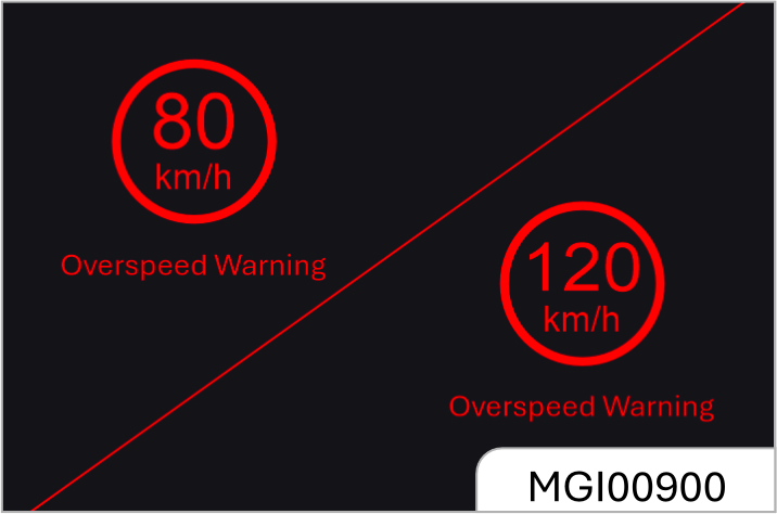
If the vehicle speed is greater than 80km/h, the meter will make an audible alarm sounds and displays alarm icon. If the vehicle speed is always more than 80km/h then every two minutes, the alarm will indicate the over speed driving. The "OK" button removes the icon from display.
Alarm will stop warning when the speed comes below 75km/h, then again over 80km/h, it will be warn for overspeed.
If the vehicle speed is more than 120km/h, the alarm will come continuously, and icon is always displayed. You can use the "OK" button to remove the icon.
Alarm will stop warning when the speed comes below 115km/h, then again over 120km/h, it will be warn for overspeed.
SCR (Selective Catalytic Reduction) Warning Light

The Low Diesel Exhaust Emissions Additive Diesel Exhaust Fluid (DEF) indicator light illuminates when the Diesel Exhaust Fluid (DEF) level is low.
Fill the Diesel Exhaust Fluid (DEF) tank as soon as possible with at least 5 liters of Diesel Exhaust Fluid (DEF).
Diesel Particulate Filter Indicator

The indicator will illuminate when DPF is blocked completely / partially. It does not affect the operation of the vehicle, but if it is due to blockage of DPF, it may affect engine power performance. After this warning light is ON, please drive vehicle at a constant speed of 70-80km / h for a while. Release the throttle for a while, repeat the process. Do it 3 or 4 times. If the indicator is still running after running at high speed, please go to the service center for rectification.
Fuel Water Indicator Light*
This indicator will illuminate when the water is mixed with the fuel.
Once the light glows, immediately drain the water through the bottom of the water separator / fuel filter. Release the water to drain, otherwise it will cause damage to oil injection Parts. If the indicator is still glowing please contact the JSW MG Authorized Service Centre for rectification if necessary.
Engine Hood Open Indicator*

This indicator will illuminate when the engine hood is opened or it is not properly closed.
Vehicle − Start / Stop Fault Indicator

This indicator illuminates when vehicle start / stop function is not functioning.
Glow Plug Indicator*

This indicator will illuminate when the glow plug is working on diesel.
This means that the engine is warming up. Do not start during this period, once the light is switched off then only start the engine. This will make the startup process very smooth.
48v System Failure Warning Light*

This indicator will illuminate when the 48V hybrid system not working.
Please contact the JSW MG Authorised Service Centre as soon as possible.
3.6 Audio Entertainment System
3.6.1 Audio Control Buttons on
Steering Wheel*
Type 1
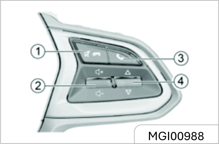
-
Mute or Call Hangup Button
It is used to sound off or hang up a Bluetooth telephone call.
-
Volume Adjustment Thumbwheel
Pull the thumbwheel up and down to adjust the sound volume.
-
Bluetooth Setup or Call Answer Button
Press the button to enter the Bluetooth interface or answer the Bluetooth telephone call.
-
Song Selection / Station Switch Thumbwheel
Pull the thumbwheel up and down to select the station or song.
Type 2
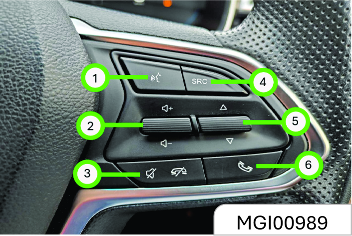
-
Voice Commend
It is reserved with no role to play for the time being.
-
Volume Adjustment Thumbwheel
Pull the thumbwheel up / down to increase / decrease the volume.
-
Mute or Call Hangup Button
It is used to sound off or hang up a Bluetooth telephone call.
-
Audio Source Selection Button
Press the button to switch among audio sources such as radio / USB / Bluetooth music.
-
Song Selection / Station Switch Thumbwheel
Pull the thumbwheel up / down to select the next / previous station or song.
-
Call Answer Button
Press the button to answer Bluetooth phone calls or enter the Bluetooth interface.
3.6.2 Driver Information and
Entertainment
For details about functional description of the & Navigation system, please refer to the vehicle system Infotainment manual available in the Head Unit User Manual Section.
If the HU is not activated and is not having network connection, a QR code will be displayed, user can scan it and download on the mobile browser.
If HU is activated and have network connected, the User manual QR Code will be downloaded & displayed in the English readable format on the same screen of HU.
Please note that whenever there will be P0P up on Infotainment system for Software/FOTA update, please update the HU software for new features and system performance enhancement.
At the same time, always ensure your handheld device (Android & IOS) must be on latest version. To get the latest version, check the software update in Phone settings.
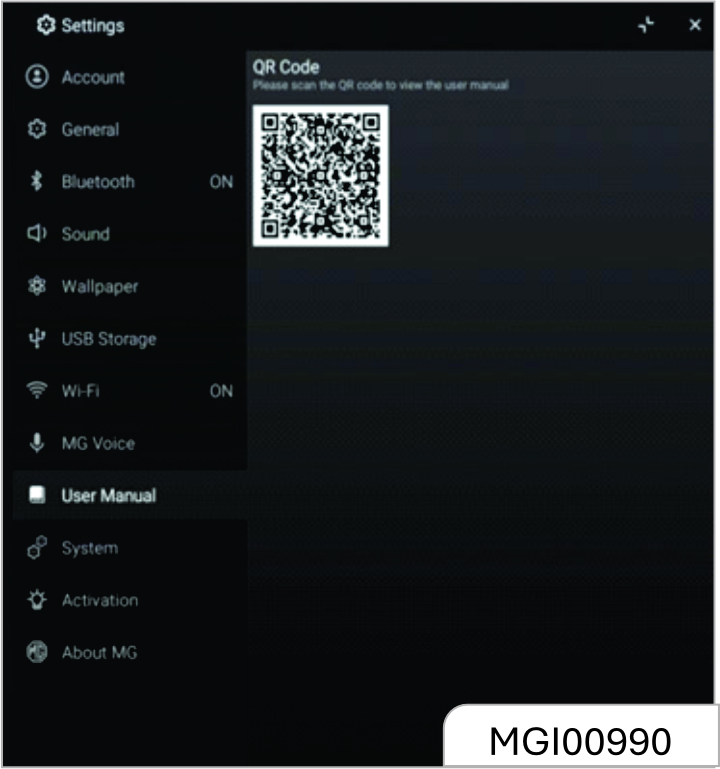
As the model configuration or the supporting manufacturers are different, the audio entertainment system function, the display interface and the operation method may be different, such as video and entertainment, navigation, reverse camera, Bluetooth and telephone calls.
Inspection before Repair
If you feel a bit of misgiving about certain audio function, before driving the vehicle to the Service Center for repair, please first read the directions given in the product instructions carefully and then check and operate according to the following table. This can help you remove the fault.
| The host does not work and no information is shown on the screen. | Take out the host from the instrument panel, and then check the host fuse and connector to the vehicle. |
| The host works but no sound can be heard or the sound volume is very low. | Increase the sound volume and check the front/rear and left/right balance setup of the horn. |
| The device body is a little hot. | The device heats normally as it works. |
| The radio cannot search for the desired station. | Inspect whether the antenna is fully stretched and connected correctly. Inspect whether the antenna amplifier in the vehicle has been damaged. Signal of the desired station is too weak and please tune manually. |
| Certain audio files cannot be played via USB connection. | Please confirm whether the device supports such audio files. Refer to the vehicle audio system instructions. |
| The sound volume fluctuates as MP3 songs are played. | As MP3 songs are of wide sources and no uniform standard applies. The reason can be that the volumes of MP3 songs are different as they are compressed. Please turn the volume knob to adjust in case of this. |
| The singer/track/song name cannot be displayed. | The device does not support text display of the audio file. |
| The music pauses intermittently as it is played. | The reason can be that the format of the music file is different as it is compressed. |
|
Songs stored in the memory device cannot be read. MP3 songs cannot be read via an all-in-one USB adapter. |
Please confirm that the storage partition form of the memorizer is FAT16 or FAT32 as it is checked in the computer; if not, please make new setup on the computer to change the format into a standard applicable to the device requirement. This device only supports song reading via an adapter with only one USB port. |
| Noise can be heard. | The noise can be produced by the device used to record the original audio file or it may be the noise existed at the time of recording. Please use other players to play the file and then confirm whether the problem lies in this device. |
| If the fault still cannot be removed, please go to the JSW MG Authorised Service Center for inspection. Never disassemble the host to repair it on yourself. | |
Navigator Upgrading*
When the navigator cannot display comparatively new main roads, it is time to update and upgrade the map data.
For details, please refer to the navigation system instructions.
After upgrading, the map may still fail to display all the roads which are recently completed and open to traffic. It is normal that certain roads can be displayed only on an upgraded map of a follow up version.
3.7 Heating, Ventilation and Air Conditioning (HVAC)
3.7.1 Air Outlet
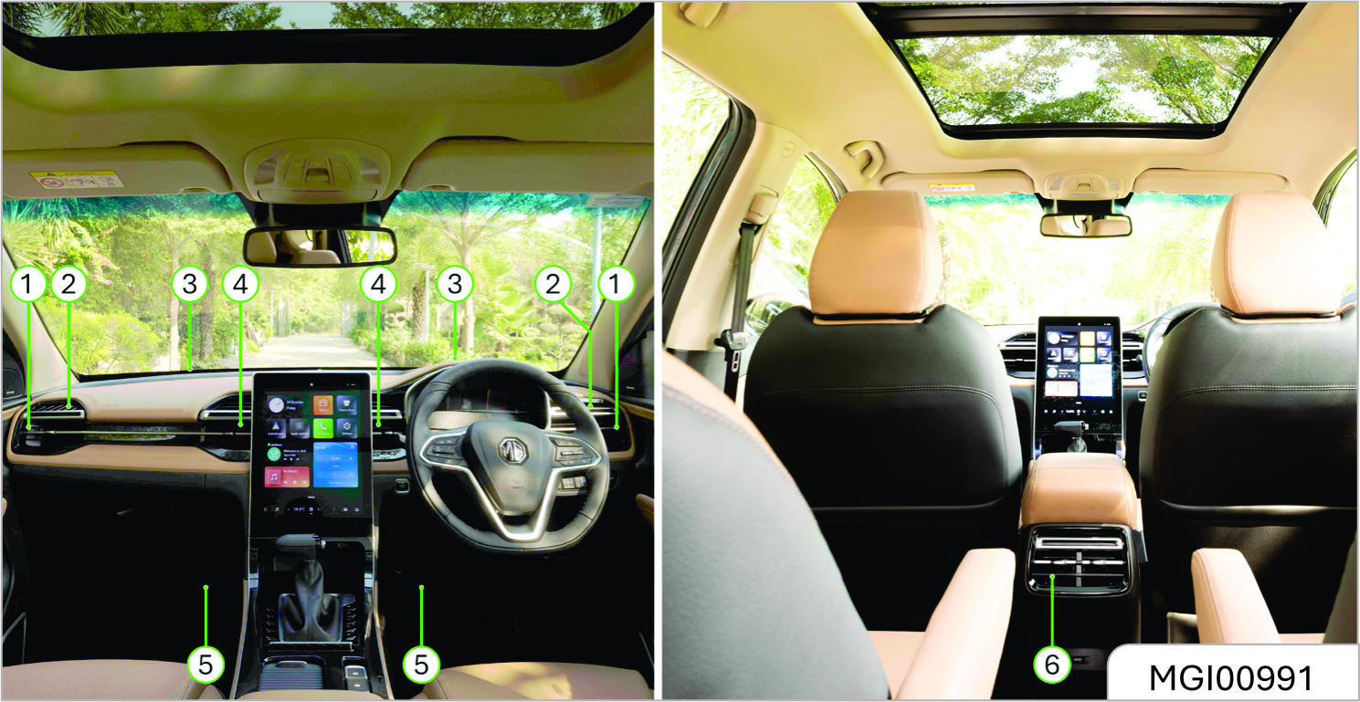
- Side Air Outlet
- Front Door Window Defogger Air Outlet
- Front Windshield Defogger Air Outlet
- Central Air Outlet
- Floor Air Outlet
- Console Air Outlet
Side Air Outlet
You can divert the air to both sides of the front riding area or the side door windows by operating the two adjustable side air outlets. Beside each air outlet, an air volume adjustment switch is located and you can operate the switch to adjust the air volume.
Front Door Window Defogger Air Outlet
The front door window defogger air outlet is used to divert the air to the side door window, mainly to the outside rearview mirror area.
Central Air Outlet
You can decide the flow direction of the air from the two adjustable central air outlets.
Front Windshield Defogger Air Outlet
The front windshield defogger air outlet is used to divert air to the front windshield.
Floor Air Outlet
The floor air outlet is used to divert the air to the front foot area.Console Air Outlet
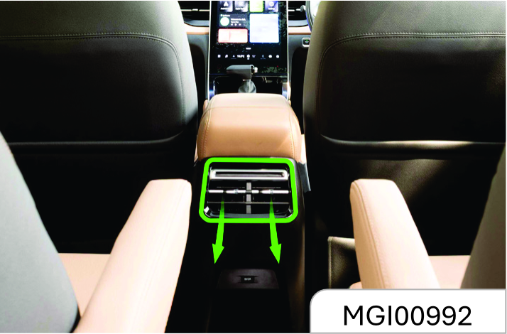
If equipped, the air outlets are located on the back of the armrest between the two front seats. They can divert the air to the rear passenger area.
Rear Air Outlet*
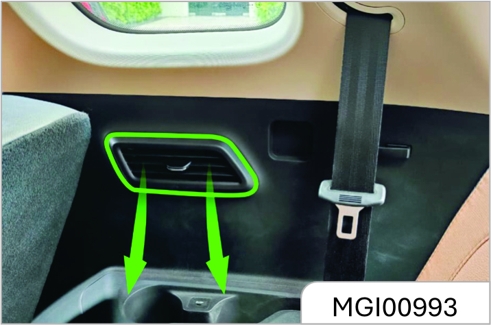
There is two rear air outlet for the 7 seater variant. You can decide the flow direction from the adjustable air outlet.
3.7.2 Air Conditioning
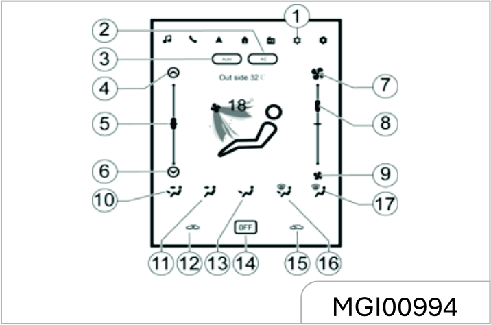
- A/C Interface
- A/C Key
- Auto Key
- Temperature Rise Key
- Temperature Adjustment Slider
- Temperature Drop Key
- Air Volume Increase Key
- Air Volume Adjustment Slider
- Air Volume Decrease Key
- Face-Foot Mode Key
- Face Mode Key
- Internal Circulation Mode Key
- Foot Mode Key
- OFF Key
- External Circulation Mode Key
- Foot/Defrosting Mode Key
- Front Defrosting Mode Key
Temperature Control Key
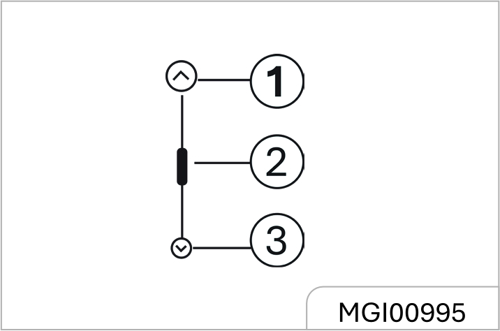
The temperature control key is used to control the air temperature at the vent. The temperature can be controlled by slider and increase/decrease key.
In A/C state, click the ^ key once. The set temperature display increases 1 gear, with the maximum of Gear 8. Click the v key once. The set temperature display decreases 1 gear, with the minimum of Gear 1.
In AUTO state, click the ^ key once. The set temperature display increases 0.5°, with the maximum of 32°. Click the v key once. The set temperature display decreases 0.5°, with the minimum of 18°.
You can also adjust the A/C temperature via temperature slider.
Once the temperature reaches the hottest (coolest) extent, if you pull the switch up again, the temperature stays unchanged.
Fan Control Key
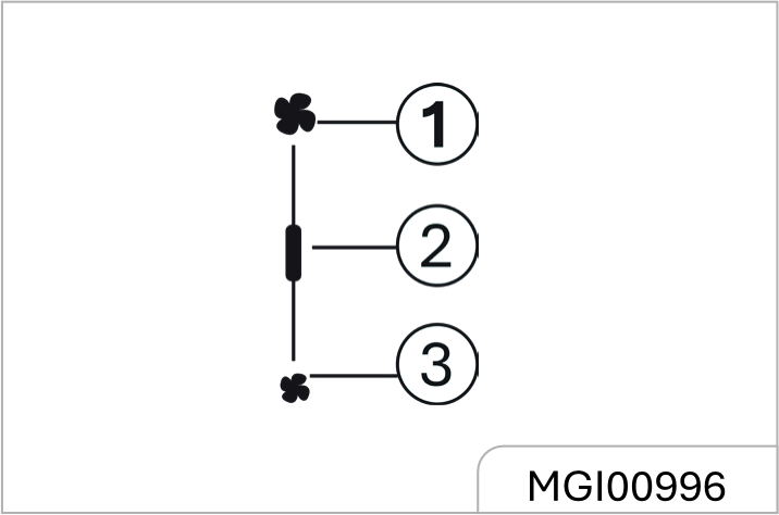
You can control the air volume at the air outlet via fan control key. The air volume can be controlled by slider and increase/decrease key. Click the once. The air volume display increases 1 gear, with the maximum of Gear 8. Click the once. The air volume display decreases 1 gear, with the minimum of Gear 1.
Air Distribution Mode
One of the following five positions can be selected in the air distribution mode according to the required airflow direction.
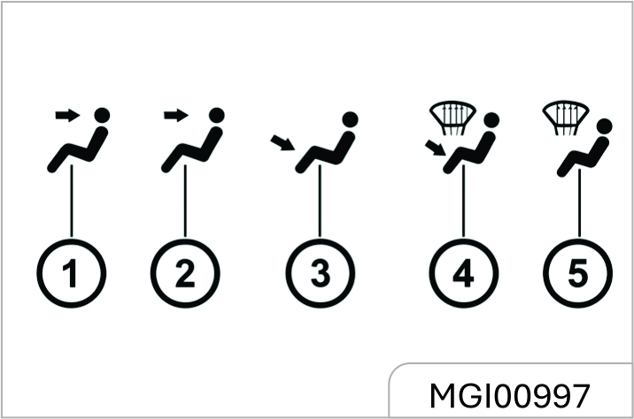
- Face-foot mode key
- Face mode key
- Foot mode key
- Foot/Defrosting mode key
- Front defrosting mode key
Electronic Air Conditioning Control Panel Type 1
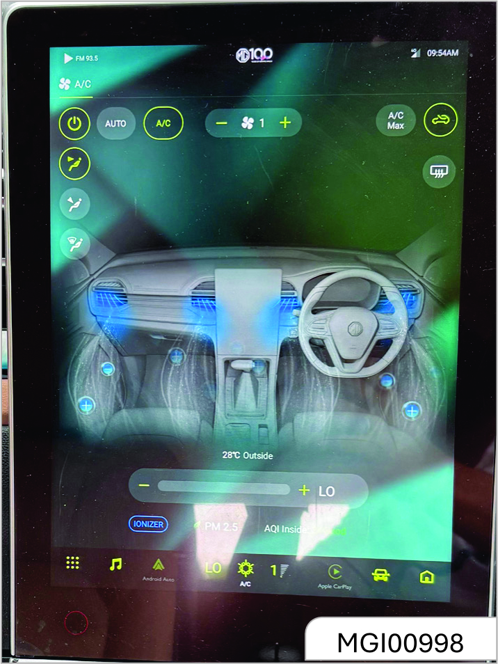
Temperature Control Key Type 1 Panel
Click to enter Air Conditioner interface.
 Click to turn on or turn off the Air Conditioner.
 Click to change the air distribution
mode to face mode.
Click to change the air distribution
mode to face mode.
 Click to change the air distribution mode to foot mode.
 Click to change the air distribution
mode to defrosting mode.These 3
modes also can be selected two
modes at the same time.
Click to change the air distribution
mode to defrosting mode.These 3
modes also can be selected two
modes at the same time.
 Click to enter auto modes.
The temperature, mode,air volume,
internal and external circulation will
automatically adjust according to the
interior environment.
Click to enter auto modes.
The temperature, mode,air volume,
internal and external circulation will
automatically adjust according to the
interior environment.
 Click to turn on the compressor to
enable the cooling system.
Click to turn on the compressor to
enable the cooling system.
 Click "+"or "-"to increase/
decrease the air volume
Click "+"or "-"to increase/
decrease the air volume
 Click to set the maximum air volume
and lowest temperature.
Click to set the maximum air volume
and lowest temperature.
 Click to switch the recirculation or
fresh air circulation.
Click to switch the recirculation or
fresh air circulation.
 Click to turn on rear defrosting
mode.
Click to turn on rear defrosting
mode.
 The outside temperature is
showing.
The outside temperature is
showing.
 Click "+"or "-"to
increase/decrease the temperature. The
range is L0,18,32,HI.
Click "+"or "-"to
increase/decrease the temperature. The
range is L0,18,32,HI.
 Click to turn on the ionizer
function to purify the air inside.
Click to turn on the ionizer
function to purify the air inside.
 The AQI data and level
in the car is showing.
The AQI data and level
in the car is showing.
Air Distribution Mode
Face Mode (
 )
)
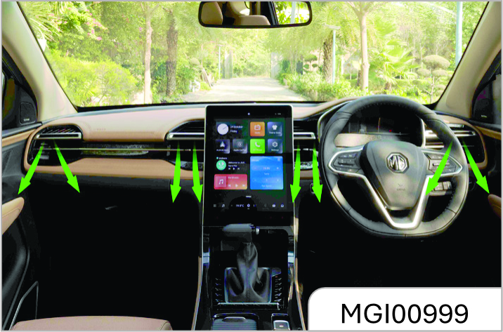
In this mode, the air flows out from the central air outlet, the side air outlet and the console air outlet*.
Face-foot Mode Key (
 )
)
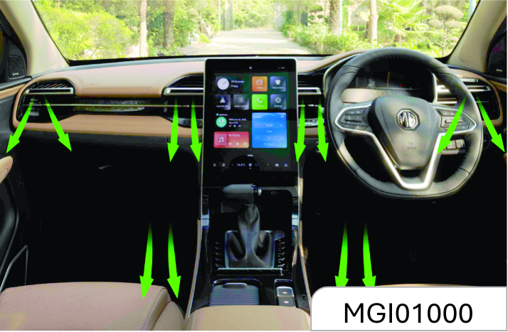
In this mode, the air flows in two directions. Half of the air flows out from the floor air outlet and the front seat lower air outlet; the remaining air flows out from the central air outlet, side air outlet and console air outlet*
Foot Blowing Mode (
 )
)
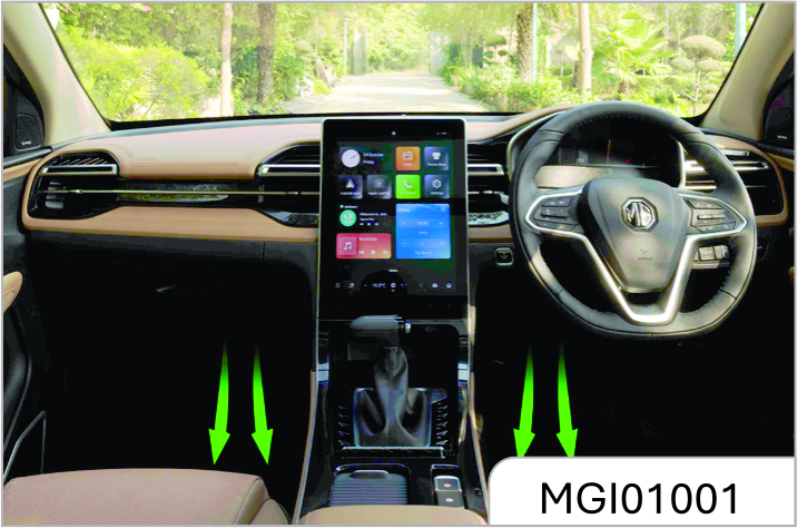
Most of the air flows out from the floor air outlet and the front seat lower air outlet; little amount of air flows out from the windshield and front door window defroster air outlet and the ide air outlet.
Foot / Defrosting Mode (
 )
)
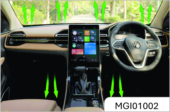
In this mode, air flows out from the front windshield defroster air outlet, the front door window defroster air outlet, the floor air outlet, the front seat lower air outlet and the side air outlet.
Front Windshield Defrosting Key
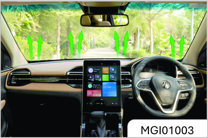
Press the button to select the front windshield defroster mode.
Press the front windshield defroster button and the air volume ascends to Range 6 automatically. If the air volume is already higher than 6 before the button is pressed, it will remain at same speed.
As you switch from the air blow mode to the defroster mode, the indicator below the button illuminates. As you turn on A/C function, the indicator on the A/C button illuminates.
The air circulation mode switches to external circulation. Press the button again to turn off the front defroster mode and the system restore to the state before defrosting.
Internal / External Circulation Mode Key.
You can press this button during driving on a dusty road, or when you want to prevent the exhaust or outside smoke entering inside, or when you want to quickly decrease or increase temperature in the passenger area. The internal circulation icon displays in white, and the interior air is circulated internally.
Press this key to switch to the external circulation mode. The external circulation icon displays in white, and the internal circulation icon is displayed in grey. The air circulates externally.
The system memorizes the previously set air circulation mode the next time you start the vehicle.
You may feel tyred and sleepy after long- time driving in the internal circulation mode.
Please switch to external circulation mode on a regular basis to acquire fresh air.
After the air conditioning system is turned on, you can find water drops in the lower area of the engine compartment. The water drops are formed as moisture in the air condenses on surface of the air conditioning system component, which is a normal phenomenon.
As the air conditioning compressor works, it consumes certain engine power. This is the reason why you may find that the vehicle power performance decreases when the air conditioning refrigeration function is activated.
The air conditioning system cannot work if the fan control thumbwheel is turned to OFF position.
Cool Air
Fast Cooling
To cool down fast in scorching hot days or after the vehicle is kept under the blazing sun for a long time:
- Open the door windows a little to expel the hot air inside.
- Turn on the air conditioning (A/C) system. (The indicator illuminates at this time).
- Activate the internal circulation mode
- Switch the air distribution mode to
face mode (
).
- Adjust the temperature to the maximum coolness.
- Adjust the fan speed to the maximum.
Normal Cooling
- Turn on the air conditioning (A/C) button. (The indicator illuminates at this time.)
- Activate the internal circulation mode.
- Switch the air distribution mode to
face mode (
) or dual mode (
 ).
).
- Adjust the temperature to the cool air area.
- Adjust the fan speed to the desired value.
Warm Air
Rapid Heating
Activate the rapid heating mode to increase the passenger area temperature quickly. It is prohibited to activate this mode for a long time, otherwise the inside air quality will decrease and fog can form on the windows. To clear up the fog on the windows, turn off the internal circulation mode so that fresh air enters inside.
To acquire the warmest air:
- Turn off the air conditioning (A/C) system. (The indicator goes out at this time.)
- Activate the internal circulation mode.
- Switch the air distribution mode to
foot mode (
 ).
).
- Adjust the temperature to the maximum warmness.
- Adjust the fan speed to the maximum.
Normal Heating
- Turn off the air conditioning (A/C) system. (The indicator goes out at this time.)
- Activate the external circulation.
- Switch the air distribution mode to
foot mode (
) or dual mode (
).
- Adjust the temperature to the warm air area.
- Adjust the fan speed to the desired value.
Ventilation
Dual Mode
This mode is applicable to cool and sunny days. Warm air is controlled to flow to the floor area and outside cool air is controlled to flow to upper portion of the compartment.
The method to use this setup is:
- Disable the internal circulation key. (The indicator goes out at this time.)
- Switch the air distribution mode to
dual mode (
).
- Adjust the temperature to the desired value.
- Adjust the fan speed to the desired value.
Ventilation
To control the air to flow out from the central air outlet and the side air outlet:
- Turn off the air conditioning (A/C) system. (The indicator goes out at this time.)
- Activate the external circulation mode.
- Switch the air distribution mode to
face mode (
) or dual mode (
)
- Adjust the temperature to the cool air area.
- Adjust the fan speed to the desired value.
Rapid Defrosting and Defogging
Please operate in the following steps in cold weather:
- Air conditioning switch (A/C): ON (southern area) or OFF (northern area)
- Air inlet mode: external circulation mode (the indicator turns off )
-
Air distribution mode:
- Temperature switch: red zone (warm air)
- Air volume switch: to the maximum
- Turn the air distribution knob to the
foot / defrosting (
) position to
keep the front windshield clean and
divert the warm air to the floor.
Please operate in the following steps if not in cold weather:
- Air conditioning switch (A/C): ON
- Air inlet mode: internal circulation
mode (the indicator turns on) (
 ).
Switch it to the external circulation
mode (the indicator turns off ) after
the fog lifts.
).
Switch it to the external circulation
mode (the indicator turns off ) after
the fog lifts.
- Air distribution mode: (
) or (
) .
- Temperature switch: to the area that ensures passenger comfort.
- Air volume switch: to the maximum
At the beginning of defrosting and defogging with the warm air, the fog can become thicker, please take care to ensure driving safety.
Rear Fan Control Switch*
The switch located at the left rear cup holder for the 7 seater variant. Press the air conditioner switch to turn on/off the A/C. You can press the arrow button to raise or lower the air volume for ther rear air outlet.
3.8 Lighting
3.8.1 Outside Lighting
Lighting Switches
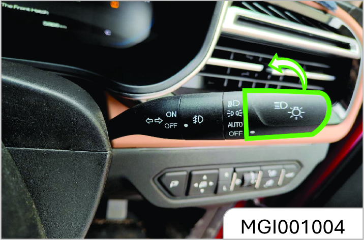
To switch ON or OFF the headlamp, tail lamp and parking lamp, please turn the end of the combination switch control lever
The lighting switch has 3 positions and they represent different lighting functions:
OFF= All the lamps are turned off.
AUTO= Automatic Light Control turns the lights on whenever the sensor, in the instrument panel, senses dark conditions. The system will activate the lights when the car is driven in a enclosure, such as a parking garage. Heavy overcast conditions can cause the lights to switch on.
 = The position lamp, license plate
lamp instrument panel lamp and
backlight of all the panels illuminate.
= The position lamp, license plate
lamp instrument panel lamp and
backlight of all the panels illuminate.
 = The low beam lamp and all lamps
mentioned above illuminate under the
precondition that the ignition switch is
turned to ON position.
= The low beam lamp and all lamps
mentioned above illuminate under the
precondition that the ignition switch is
turned to ON position.
High Beam
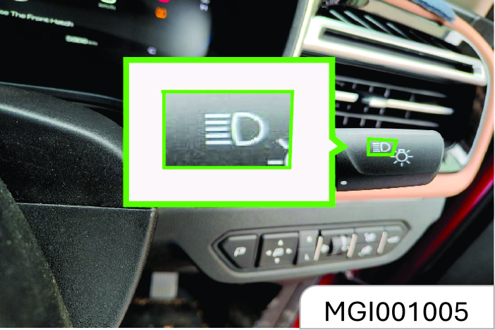
To turn on headlamp high beam:
- Ensure that the ignition switch is in ON position;
- The headlamp is in a low beam state;
- As is shown in the figure, push the combination switch control lever towards the instrument panel.
The headlamp high beam indicator illuminates when the headlamp high beam is turned on. To switch from headlamp high beam to low beam, pull the control lever towards the opposite direction until it returns to the normal position.
Automatic Headlamp ON / OFF
When the ignition switch is in ON position, turn the combination switch lever to AUTO Position. This activates automatic headlamp ON / OFF function.
The system’s light sensor recognizes the environment’s light and dark condition.
Headlamp Flashing
To activate headlamp high beam flashing, please pull the combination switch control lever toward yourself and then release it. The control lever will return to the normal position as you release it.
Before you release the control lever, the headlamp high beam keeps illuminated.
While approaching incoming vehicle or the vehicle ahead, please use low beam. This is because headlamp high beam can make other driver feel temporarily blind and cause collision as a result.
Automatic Wiping
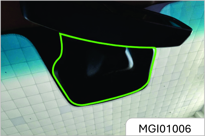
The sensor is installed on the front windshield Light and rain sensors are used to sense light and rain. The control module provides sensing signals for bad / good lighting & amount of water vapor / rainfall on the surface of the glass.
The automatic control (AUTO) function of the wiper / headlamp acts accordingly
Stains or snow and ice can affect the sensor’s performance. Please clean up the glass on time.
Hazard Flasher Type I
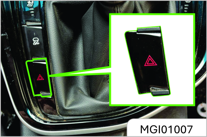
Hazard Flasher Type II
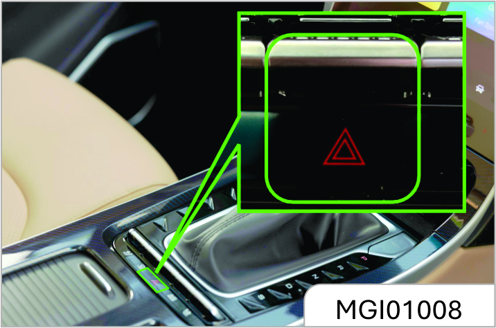
Press
 to turn on/off the hazard flasher.
Please turn on the lights manually in a dense fog environment. The lighting system may not automatically turn ON because of dense fog. Automatic lighting control is just an auxiliary function. The driver should use lights as per the requirement of environment.
Turn and Lane Change Signal Lamp
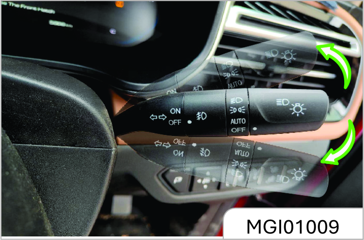
To turn on the Turn and Lane Change Signal Lamp, the ignition switch must be in ON position.
Control lever upward = left turn signal lamp
Control lever downward = right turn signal lamp
After cornering, the turn signal interrupts automatically, and the control lever returns to the normal position.
To change the lane, you can pull the control lever to a halfway position
(not reaching the turn signal lamp position) and keep pulling it. After lane change, release the control lever and it will return to the normal position automatically.
A rear turn signal lamp is integrated on the rear combination lamp and the rear bumper of your vehicle respectively. If you turn on the turn signal lamp with the liftgate open, the turn signal lamp on the rear bumper will illuminate. This ensures that a turn signal is sent to the drivers behind even when the liftgate is open.
Auto Turn Feature*
When vehicle turns to left or right,lane change signal lamp indicator left or right ON by itself.

3.8.2 Fog Lamp
Steering Assist Lighting Function*
During steering, the two front fog lamp will illuminate to provide auxiliary lighting if certain conditions are satisfied. These conditions are:
- The engine is running.
- The vehicle speed is 35 Km/h.
- The low beam lamp is turned on.
- The steering wheel angle is >60° or the turn signal lamp switch is turned on.
As the front fog lamp illuminates, the front fog lamp indicator on the instrument panel also illuminates.
The steering assist lighting function deactivates and the front fog lamps go out after a while under any of the following condition:
- The steering wheel angle is 30° or the turn signal lamp switch is turned off.
- The ignition switch is turned to a position other than ON.
- The vehicle speed is > 40 Km/h;
- The low beam lamp is turned off.
Front Fog Lamp*
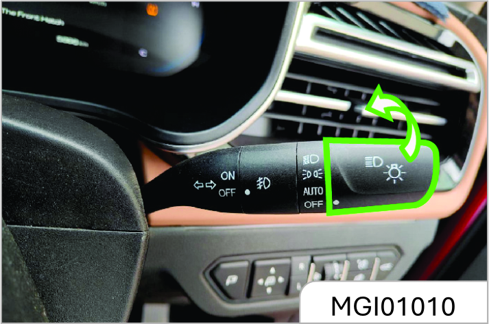
When the ignition switch is turned to ON position, and the headlamp functions as a position lamp or in a low beam state, turn the ring button in the middle of the combination switch to ON (connected) position to turn on the front fog lamp. Turn the ring switch to OFF (disconnected) position to turn off the front fog lamp.
Rear Fog Lamp
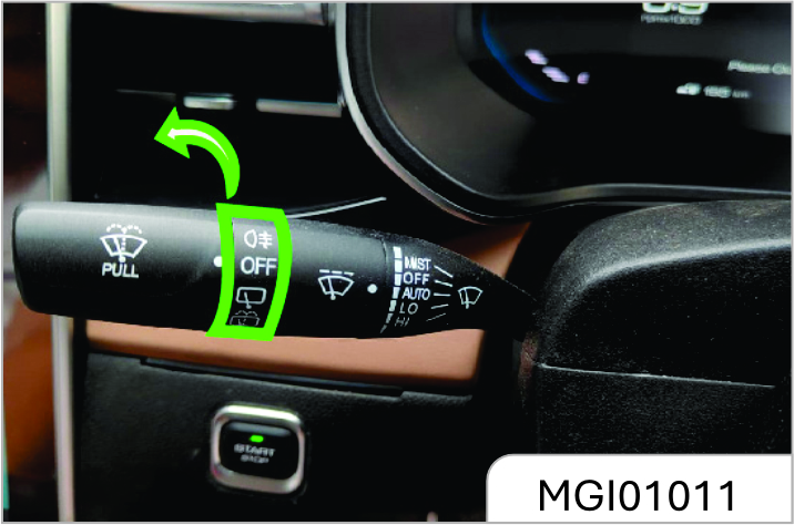
When the headlamp is in low beam state or the front fog lamp is turned on, turn the rear wiper control knob to "s" position and then release it to turn on the rear fog lamp. Turn the knob again to turn off the rear fog lamp.
If the low beam lamp or front fog lamp is turned off with the rear fog lamp turned on, the rear fog lamp keeps on.
Backup Lamp
The backup lamp illuminates after you turn on the ignition switch and shift to reverse gear.
Stop Lamp
The stop lamp illuminates as you depress the brake pedal.
Day Running Lamp*
The day running lamp turns on automatically as the engine starts, it goes out automatically as the position lamp is turned on.
Headlamp Levelling
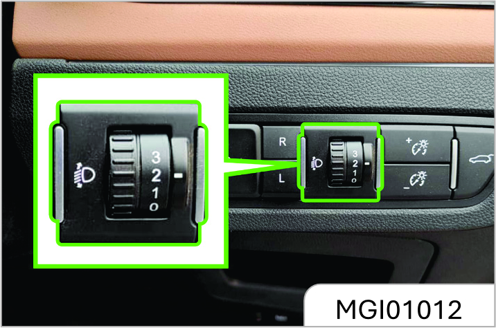
The headlamp leveling knob is located at the right side of the instrument pane.
Please adapt the headlamp illuminate range to the vehicle load so as to acquire the best lighting effect and avoid dazzling. Turn the knob to the desired position:
0 = front seats occupied
1 = all seats occupied
2 = all seats occupied with the luggage compartment loaded
3 = driver’s seat occupied with the luggage compartment loaded
Headlamp OFF Delay
To trigger off headlamp OFF delay function, turn off the headlamp and pull the light control lever towards the steering wheel within one second for twice after you shut down the engine and turn the ignition switch to ACC or LOCK position, or after you pull out the key. After remote locking, the low beam lamp will turn off automatically 30s later, if the vehicle is not remotely locked, the low beam lamp will turn off automatically 10 minutes later.
Lamp ON Reminder
If any lamp switch is not turned to OFF position after you turn the ignition switch to LOCK position or pull out the key, the buzzer will send out alarm sound as the driver’s door is opened. The alarm sound stops after the lamp is turned off.
Inside Lighting
Front Reading Lamp
Type 1
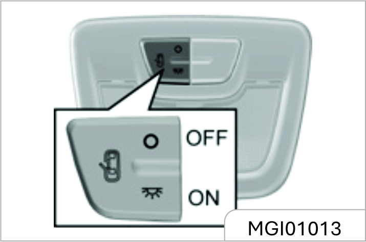
The lamp has 3 working positions.
 : The lamp illuminates and keeps
illuminated until it is manually turned
off.
: The lamp illuminates and keeps
illuminated until it is manually turned
off.
 : The lamp gradually illuminates as
any door is opened; it works for a while
and then gradually goes out after all the
doors (including liftgate) are closed.
: The lamp gradually illuminates as
any door is opened; it works for a while
and then gradually goes out after all the
doors (including liftgate) are closed.
 : The lamp does not illuminate
even a door is opened.
: The lamp does not illuminate
even a door is opened.
Type 2
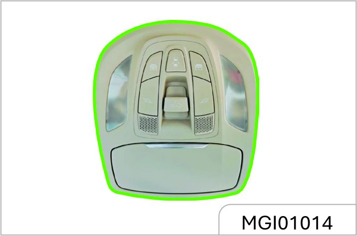
 or
or
 : Press the button to turn on
the left/right reading lamp and press it
again to turn the lamp off.
: Press the button to turn on
the left/right reading lamp and press it
again to turn the lamp off.
 : The reading lamp gradually
illuminates if any door is opened
(including liftgate) as the button is
pressed. It gradually goes out after all
the doors are closed.
: The reading lamp gradually
illuminates if any door is opened
(including liftgate) as the button is
pressed. It gradually goes out after all
the doors are closed.
Please avoid usage of the inside lamps during driving in darkness. A bright passenger compartment can reduce the visibility outside and cause collision as a result.
Rear Reading Lamp
Type-1
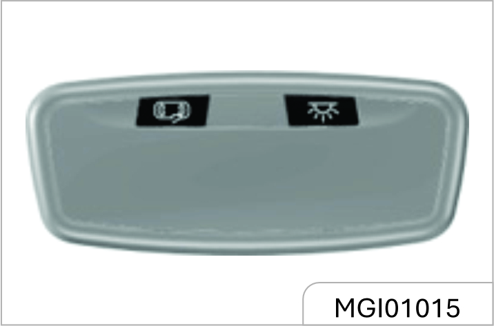
The rear reading lamp has 2 working buttons:
: Press the switch and the lamp
illuminates. It will not go out until the
switch is pressed again.
: The lamp gradually illuminates if
the switch is pressed and any door is
opened; it works for a while and then
gradually goes out after all the doors
(including lift gate) are closed.
Type-2
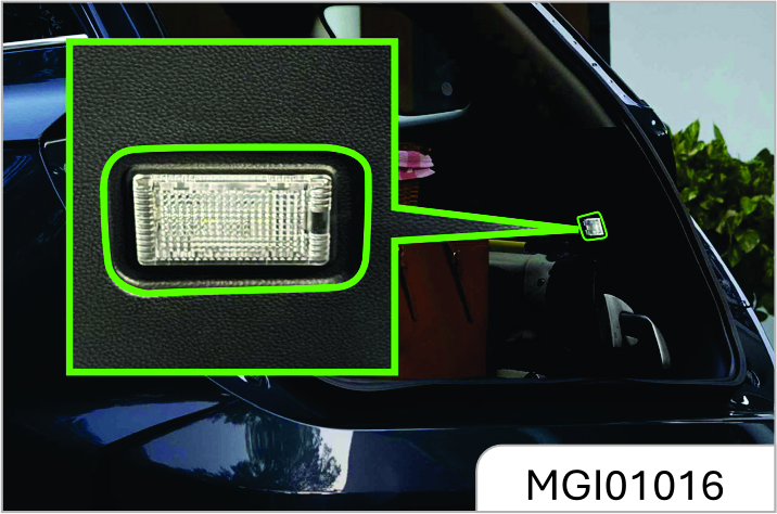
For certain models, two reading lamps are installed on the roof over the second row seats. You can press the reading lamp switch to turn it on/off.
Luggage Compartment
Illumination Lamp
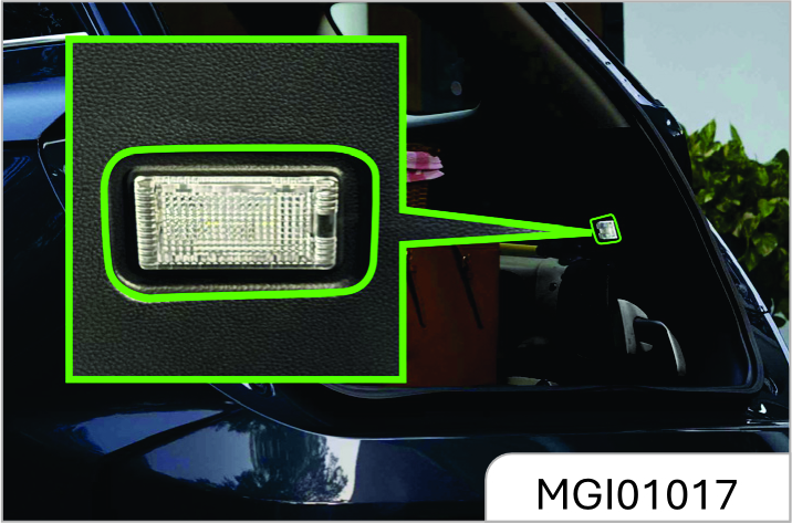
The luggage compartment illumination lamp illuminates as the liftgate is opened. It goes out after the liftgate is closed.
Please do not replace with a highpower bulb (for example, refit with a xenon headlamp) in case that the lamp burns out or an accident arises from it.
Please turn off all lamps before you leave the vehicle.
3.9 Storage
3.9.1 Storage Box
Storage Box
Instrument Panel Right Storage Box
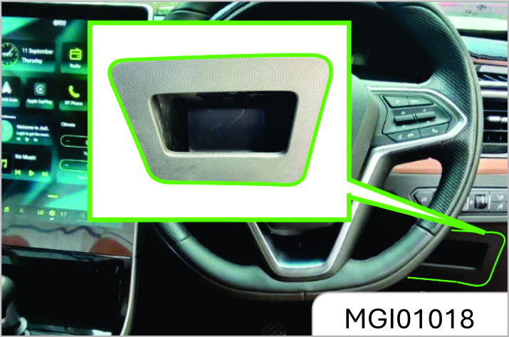
Instrument Panel Central Storage Box
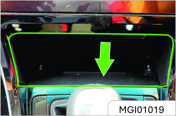
The storage box is under the air-conditioning control panel.
Armrest Storage Box
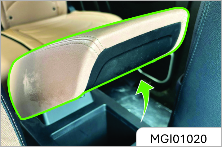
It is located between the front seats. Pull up the storage box cover to open it.
Close the storage box cover after using the box.
Glasses Box*
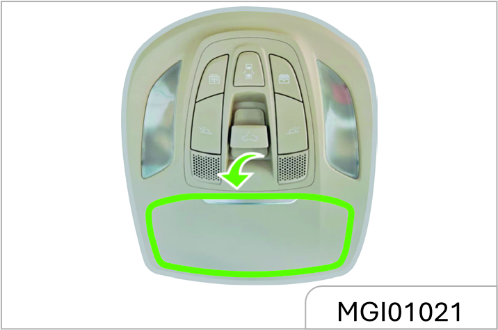
If equipped, the glasses box is located on the roof.
As shown in the figure, press the outer cover, and the glasses box will pop up automatically. Close the glasses box after use.
Console Storage Box*
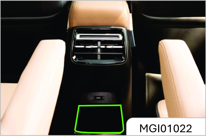
It is behind the armrest box.
Glove Box
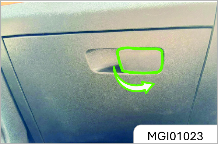
Pull the handle outward to open it. To close, push and fasten the glove box door inward.
Keep the glove box door closed when the vehicle is running to reduce the injury risks in case of accidents or emergency braking.
Seat Pocket
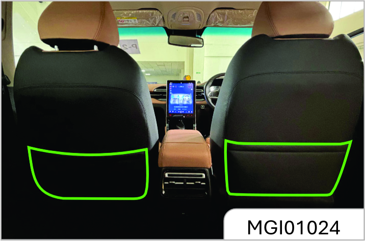
The seat pocket is located behind the front seat backrest.
Cup Holder
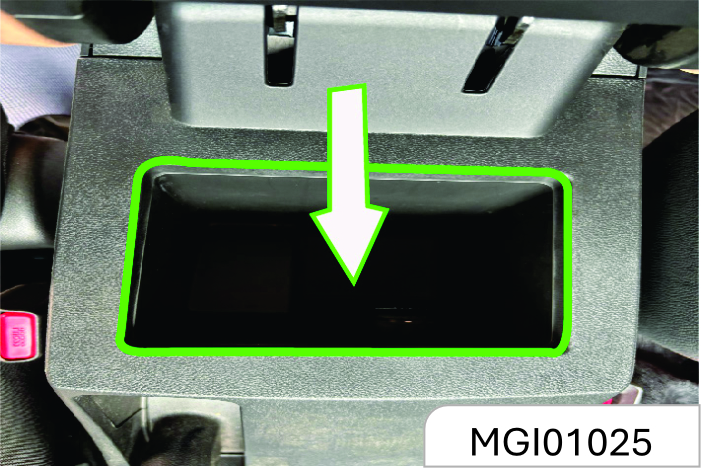
The cup holder is located on the console between the front seats. There are 2 cup holders on the rear row seat middle armrest.
Avoid sudden braking, starting and accelerating of the vehicle when the cup holder is in use to prevent liquid spillage. If hot liquid spills, it can result into burns. Such burn to the driver or co passenger could lead to loss of vehicle control & may result in accident.
- Do not place uncovered or unsecured cups, bottles, cans etc. in the cup holder containing hot liquid while the vehicle is in motion. Injuries may result in the event of sudden stop or collision.
- Keep cans or bottles out of direct sun light & do not put them in a hot vehicle. It may explode.
- Keep your drinks sealed while driving to prevent liquid spillage . Liquid spills may get into vehicles electrical/ electronic system & damage electrical/ electronic parts.
- When cleaning spilled liquids, do not dry the cup holder at high temperature. This may damage the cup holder.
When the vehicle is running, it is for bidden to place a container that contains fluid but is not covered in the cup holder. If the fluid spills out, scald may be caused, or you may lose control on the vehicle due to distraction, leading to an accident.
Door Storage Groove and Armrest
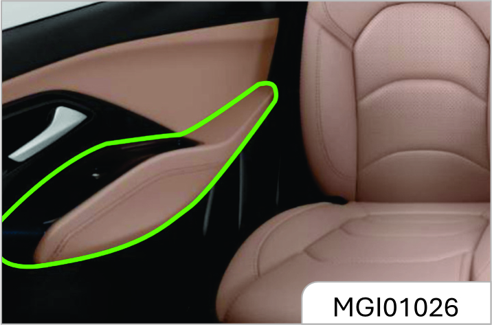
The door storage groove and armrest are located on inner side of the door panel.
Rear Side Wall Storage Groove and Armrest
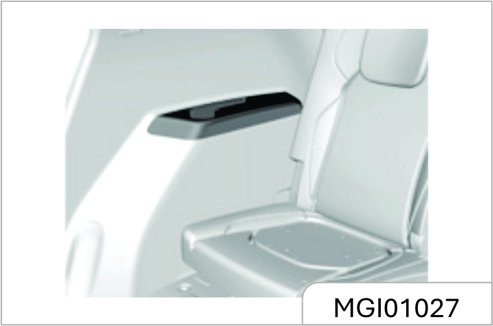
Backrest Hook
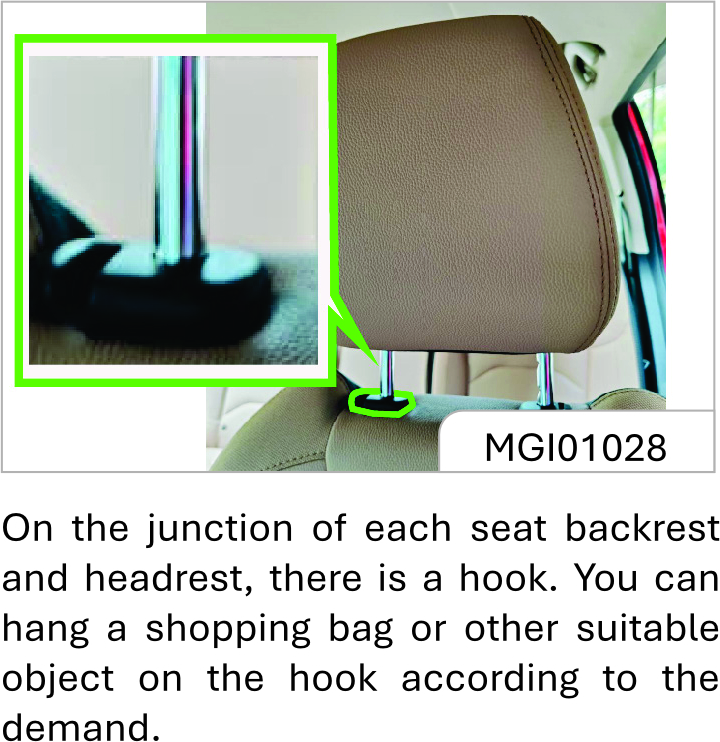
On the junction of each seat backrest and headrest, there is a hook. You can hang a shopping bag or other suitable object on the hook according to the demand.
Luggage Compartment Cargo Cover*
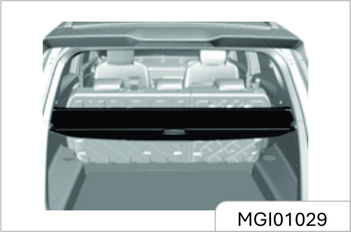
The cover is used to shield the objects in the luggage compartment.
Packing Up Luggage Cover
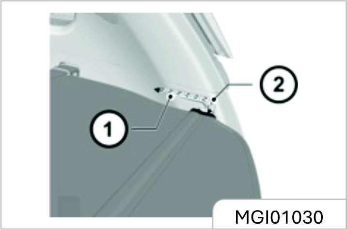
As shown in the figure, release the luggage cover plates from the guide slots on both sides of the luggage compartment, and the cover will retract automatically. To deploy the luggage cover, pull the luggage cover from the recoiler, and clamp the two ends of cover plate into the guide slots on both sides of the luggage compartment.
Luggage Cover Removal
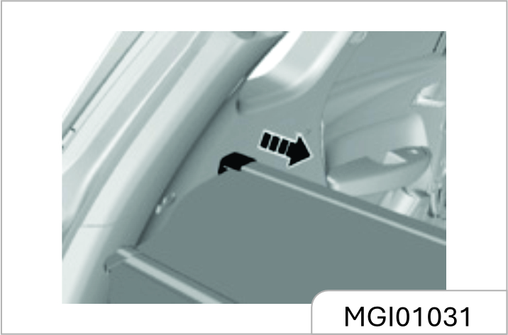
As shown in the figure, press the caps on both ends of the luggage cover recoiler toward the middle to remove the luggage cover from the vehicle.
To install the cover, press the caps on both ends toward to the middle, and align the caps to the slots and then release the caps to fix the recoiler in the slots.
Do not place any object on the luggage compartment cargo cover. On one hand, the luggage cover cannot bear loads, on the other hand, the object may hurt occupants under emergencies.
Please place and fix the removed luggage cover properly; otherwise, the removed luggage cover may hurt occupants under emergencies.
3.10 Roof Rail
The roof rail is an external trim item. To avoid damaging the vehicle, please do not use the rack to load heavy objects.
Load Information
The heavy objects inside the luggage compartment shall be placed close to the backrest. Make sure that the backrest is fastened. If objects need to be piled in layers, heavy ones shall be placed in the bottom.
- Objects scattered in the luggage compartment shall be fixed to prevent them from sliding.
- The loaded object shall not be higher than the upper edge of the backrest.
- Any object shall not be placed on the luggage cover or the instrument panel. It is forbidden to cover the air bag or other parts on the instrument panel.
- The objects loaded shall neither hinder the operation of pedals, parking brake and shift lever nor limit the free movement of the driver. Do not put any object not fixed in the vehicle.
- Do not drive the vehicle when the liftgate open.
It is forbidden to place a cigarette lighter, propane gas cylinder, perfume or other combustible / explosive materials in the vehicle. These articles may be on fire or explode when the vehicle is under high temperature for a long time.
Repair & Maintenance
4.1 General Information
Accessories and Vehicle Retrofitting Do not slide in case that the engine is out of operation.
We recommend using original spare and accessory parts and components that are approved by the company to be particularly suitable for the vehicle. We may not able to guarantee the compatibility of other products with this vehicle, even if these products meet the specified requirements or are otherwise approved.
Tips for Glass Filming
During the process of glass filming, the cleaning solution may easily enter electronic components around the instrument panel, causing electrical faults. Please complete waterproofing work before filming.
Do not retrofit the vehicle. Otherwise, the performance, durability and safety of the vehicle may be affected, problems caused by retrofitting are not within the scope of warranty.
Vehicle Storage Long-term Storage
Several months of storage of the vehicle:
- Clean the vehicle for waxing.
- Check the wax coating of engine compartment and the underbody.
- Clean and protect the rubber seal.
- Replace the engine oil.
- Drain the washer fluid reservoir.
Check coolant antifreeze agent and corrosion protection.
Adjust the tyre pressure according to the specified value under full load.
Park the vehicle in a dry and wellventilated area. Shift to Gear 1 or reverse gear to prevent the vehicle from sliding.
Close all doors and lock the vehicle.
Disconnect the clip from the vehicle battery negative terminal. Pay attention to that all systems are out of service at this time, e.g. theft deterrent system.
Vehicle being Put into Operation again:
- Connect the clip to the vehicle battery negative terminal. Enable the electronic device of power window.
- Check the tyre pressure.
- Fill the washer fluid reservoir.
- Check the engine Oil level.
- Check the coolant level.
- Check the interior, exterior and engine compartment regularly to keep the vehicle safe and reliable.
4.2 Driver Checklist
Exterior
Tyre
- Inflate tyres correctly. (Refer to "Wheels and tyres" in this chapter).
- There is no crack on tyre wall or tyre tread.
- There is no foreign matter in tread pattern.
Lamp
- It includes all driving lamps, headlamps, tail lamps, turn signal lamps, brake lamps and fog lamps.
Oil Tank
Check whether the level of fluid containers under engine hood is appropriate.
Windshield Wiper
Check the state of wiper arms and blades.
Interior
Steering
- Check whether the steering wheel is too loose (free travel).
Parking Brake
- Ensure the travel of parking brake lever is appropriate.
Instrument Panel
- Check whether all instruments, control buttons and warning lamps are functioning normally.
Rearview Mirror
- Ensure the reflecting surface of rearview mirror is in good state and clean.
- Check whether all rearview mirrors can be readjusted.
Control
- Check the brake pedal and clutch pedal for appropriate travel.
4.3 Engine Compartment
1.5T Engine
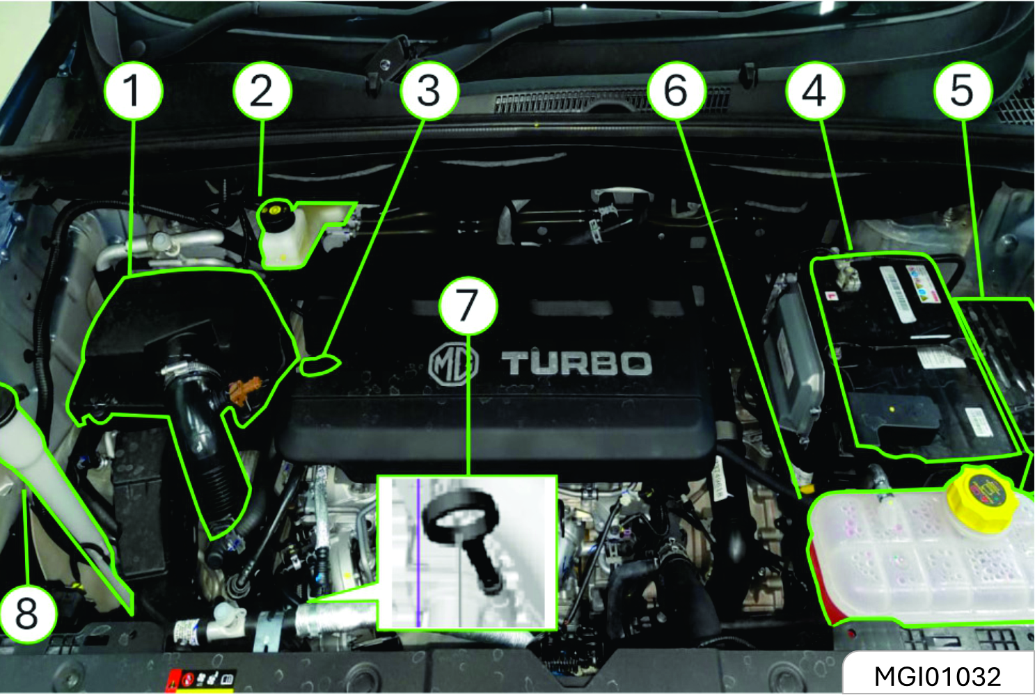
- Air filter
- Brake/clutch fluid reservoir
- Engine oil filler cap
- Battery
- Fuse and relay box
- Coolant pot
- Engine oil dipstick
- Windshield washer solvent container
2.0 Diesel Engine
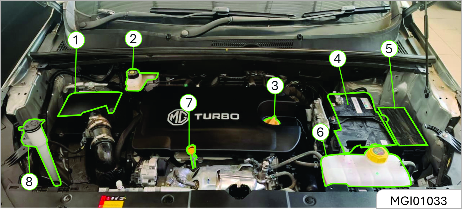
- Air filter
- Brake/clutch fluid reservoir
- Engine oil filler cap
- Battery
- Fuse and relay box
- Coolant pot
- Engine oil dipstick
- Windshield washer solvent container
4.3.1 Engine Oil
Maintain the engine oil at a proper level to ensure correct lubrication of engine.
It is normal that the engine consumes some oil.
Check the engine oil level regularly, e.g. every time parking for refueling.
If the engine oil pressure warning lamp located inside instrument panel is ON, check the engine oil level immediately
Engine Oil Level Check
- Park the vehicle on a horizontal ground.
- After the engine stops running, wait for a few minutes to have the oil back to the oil pan. For cold engine, the time for the oil returning to the oil pan will be relatively long.
- Pull out the oil dipstick and clean it.
- Insert the oil dipstick completely.
- Pull out the oil dipstick again.
- Check the engine oil on the dipstick to ensure that the oil is free of contamination.
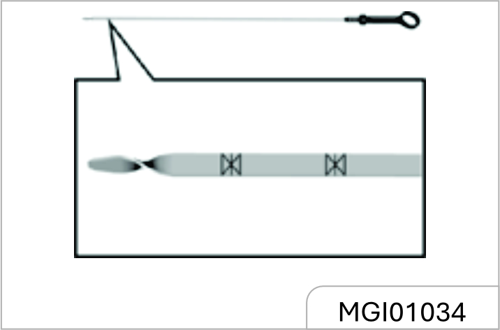
- Observe the oil level via the oil dipstick. The oil level should be between the lower limit and the upper limit.
- If the oil level is lower than the lower limit, add engine oil of the same grade to have the oil level approaching to but not higher than the upper limit. The engine oil filler cap is on the cylinder head cover. Refer to the diagram of "Engine compartment".
Engine oil is irritating and can cause illness or fatal danger in case of swallowing.
- Keep it out of reach of children
- Avoid repeated or prolonged skin contact with engine oil.
- Wash the part in contact with engine oil with soap water or hand sanitizer.
The engine oil will lose the lubricating capacity after being contaminated. Be sure to replace the engine oil in accordance with maintenance procedures. The oil filter must be replaced at the same time of engine oil replacement every time. Under harsh conditions, the replacement interval of engine oil and oil filter must be shorter than the interval specified in standard maintenance procedures.
This work requires professional skills, tools and equipment, therefore, please go to the JSW MG Authorised Service Center for help. Otherwise, it may cause personal injury or damage to the vehicle.
Harsh conditions include but not limited to:
- Frequent cold start.
- Frequent starting and stopping in case of traffic jam.
- Frequent driving for short trips.
- Frequent driving at an outside temperature of below 0°C.
- Long time idling.
- Frequent driving at low speed.
- Frequent driving under dusty conditions.
The engine oil and oil drum are harmful to human health.
Avoid repeated or prolonged exposure to engine oil. In case of contact with engine oil, wash the skin with soap water or hand sanitizer. Keep this kind of toxic substance out of reach of children.
Engine oil is irritating to the skin and can cause illness or fatal danger in case of swallowing.
It is prohibited to dispose of old engine oil and filters together with household garbage.
It shall make use of local legal waste management facilities.
Old engine oil and filters contain harmful substances that are harmful to human health and threaten the environment.
The use of non-specified or poorquality engine oil or additives will cause damage to the engine. Please consult the JSW MG Authorised Service Centre before attempting to use additives.
4.3.2 Coolant
The vehicle cooling system is filled with ethylene glycol coolant.
This kind of coolant in right mixing ratio can provide excellent anti-corrosion and antifreeze performance for the cooling and heating systems.
When the engine is in a cold state, the coolant level shall be between MIN (minimum) and MAX (maximum) marked on the coolant tank. The coolant level rises with the engine temperature rise and drops as the engine cools.
If the coolant level is lower than the MIN (minimum) mark, please go to the JSW MG Authorised Service Center for coolant filling or replacement.
Ordinary water or coolant in wrong mixing ratio will cause damage to the cooling system.
It is prohibited to use ordinary water, alcohol or methanol on the vehicle to prevent freezing.
Under pressure, hot coolant and steam may spray out, causing serious personal injury.
It is prohibited to open the coolant tank cover before the engine and radiator cool down.
The coolant is a dangerous substance.
- Avoid repeat edorprolonged exposure to coolant.
- In case of contact with coolant, wash the skin and fingernail with soap water
- Keep it out of reach of children.
- Coolant is irritating to the skin and can cause illness or fatal danger in case of swallowing.
4.3.3 Brake and Clutch Fluid
There is a brake and clutch fluid reservoir on the vehicle. The brake and clutch fluid is moisture-absorbing, and the fluid with excessive water content will reduce the efficiency of the hydraulic brake/clutch system.
Replace the fluid as per the instruction in the Manual to avoid corrosion of the hydraulic system.
Be sure to use the brake/clutch fluid recommended by JSW MG Motor. Add fluid into the reservoir to reach a proper level. The fluid level shall not be lower than the MIN (minimum) mark or higher than the MAX (maximum) mark.
The cause of excessive low brake fluid level may be leakage of brake system or normal wear of brake pad/lining. Please contact the JSW MG Authorised Service Centre to ensure that whether the system needs to be repaired. If repairs are necessary, add fluid after repair of hydraulic braking system. When the brake fluid level is lower than the lower limit, the braking system warning lamp will be on. Refer to "Braking System/EBD Warning Lamp" in Chapter "Instrument and Control Device".
Brake / Clutch Fluid Adding
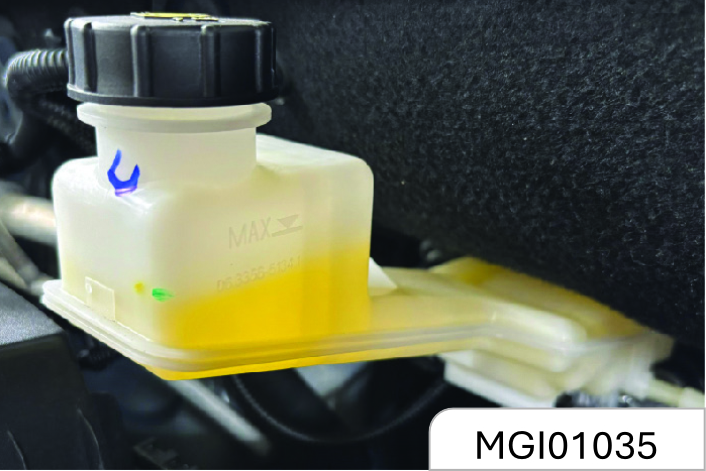
- Thoroughly wipe off the dirt around the reservoir filler cap.
- Open the filler cap.
- Add the brake/clutch fluid recommended by JSW MG Motor to reach the MAX (maximum) mark. Be careful not to spill the fluid on the paint surface. In case of spilling on the paint surface, wash the area with cold water immediately.
- Re-install the reservoir filler cap.
Auto Transmission Clutch Fluid Adding *
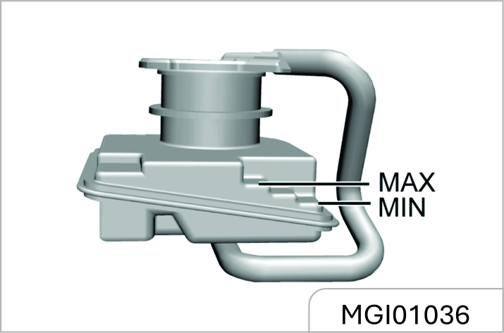
The vehicle equipped with auto transmission has an independent clutch fluid reservoir.
- Thoroughly wipe off the dirt around the reservoir filler cap.
- Open the filler cap.
- Add the clutch fluid recommended by JSW MG Motor to reach the MAX (maximum) mark. Be careful not to spill the fluid outside the reservoir. In case of spilling on the paint surface, wash the area with cold water immediately.
- Re-install the reservoir filler cap.
The level inspection and adding of clutch fluid require skills, and the fluid replacement requires specialized skills and equipment. It is recommended to go to a service centre for vehicle maintenance on time. For any help, please contact the service centre.
Before opening the filler cap, clean the area around the brake/clutch fluid reservoir filler cap.
Contamination of the brake/clutch fluid system will affect the system performance, resulting in costly repairs.
The brake / clutch fluid is irritating to the skin and eyes.
Keep the skin or eyes from contact with the brake/clutch fluid. In case of contact, wash the part in contact with the brake/clutch fluid with soap water or hand sanitizer thoroughly.
It is prohibited to dispose of the old brake/clutch fluid as household garbage. It shall make use of local legal waste management organization.
The old brake/clutch fluid and containers are dangerous and may be harmful to human health and the environment.
The brake/clutch fluid spilling over the engine may cause a fire.
An overfull fluid reservoir is not allowed. Engine fire may cause personal injury and dama g e the vehicle and other properties.
4.3.4 Transmission Fluid
Transmission Fluid Leakage Check
This work requires professional skills and equipment. To avoid personal injury or vehicle damage, it is suggested to go to the JSW MG Authorized Service Center for help.
4.3.5 Windshield Washer Solvent
Before driving, be sure that the fluid reservoir contains sufficient specified washer solvent.
In cold weather, the windshield washer solvent container cannot be overfilled.
The washer solvent will swell under low temperature due to freezing. An overfull container has no enough space for expansion, thus resulting in damages.
Please go to the JSW MG Authorised Service Centre for filling of the correct washer solvent.
Do not fill water or radiator antifreeze agent into the windshield washer solvent container. The water will lead the solution to freeze, and the frozen solution will damage the windshield washing system. The radiator antifreeze agent will damage the windshield washing system and vehicle paint.
Add windshield washer solvent:
It is suggested to use the readyto-use special washer solvent. If concentrated washer solvent is used, please add water to dilute It accordingto the manufacturer’s instructions.
Do not use tap water. Minerals or impurities contained in tap water may block lines of the windshield washer.
If the temperature is likely to fall below freezing point, use windshield washer solvent with good antifreeze performance.
4.3.6 Diesel Exhaust Fluid (DEF)
Diesel Exhaust Fluid (DEF) Injection System Failure Warning Light - If Equipped*
This warning light will illuminate along with a dedicated message on the display (If Equipped) if an unknown fluid not conforming with acceptable characteristics is inserted, or if an average consumption of Diesel Exhaust Fluid (DEF) over 50% is detected. Contact an JSW MG Authorized Service center as soon as possible.
If the problem is not solved, a specific message will appear on the Instrument Cluster Display whenever a certain threshold is reached until it will no longer be possible to start the engine.
When about 200 km are remaining before the Diesel Exhaust Fluid (DEF) tank is empty, a continuous dedicated message will appear on the instrument panel, accompanied by a buzzer sound*.
Low Diesel Emissions Additive Diesel Exhaust Fluid (DEF) Indicator Light - If Equipped*
The Low Diesel Exhaust Emissions Additive Diesel Exhaust Fluid (DEF) indicator light illuminates when the Diesel Exhaust Fluid (DEF) level is low.
Fill the Diesel Exhaust Fluid (DEF) tank as soon as possible with at least 5 liters of Diesel Exhaust Fluid (DEF).
| MESSAGE | DESCRIPTION |
|---|---|
| Diesel Emissions Additive Diesel Exhaust Fluid (DEF) Warning Messages: | |
| Low Diesel Emissions Additive Diesel Exhaust Fluid (DEF) Level Warning |
The first low level warning will be given at around 2,400 km range, and is determined according to the current consumption rate. The "Diesel Exhaust Fluid (DEF) Low Level" warning light and message will display on the instrument panel. The Diesel Exhaust Fluid (DEF) low level warning light will remains lit until the Diesel Exhaust Fluid (DEF) tank is topped up with at least 5 Liters of Diesel Exhaust Fluid (DEF). If the level is not resolved an additional warning appear whenever a certain threshold is reached until it will no longer be possible to start the engine. When 200 km are remaining before the Diesel Exhaust Fluid (DEF) tank is empty, a message will appear on the instrument panel, accompanied by a buzzer sound. When the range is at 0, the display will show a dedicated message (if equipped). In this case, the engine will not restart. It will be possible to restart the engine again as soon as Diesel Exhaust Fluid (DEF) is added; the minimum amount required is 5 Liters. Fill the Diesel Exhaust Fluid (DEF) tank as soon as possible with at least 5 Liters of Diesel Exhaust Fluid (DEF). NOTE: When the Diesel Exhaust Fluid (DEF) tank is empty, and the vehicle is stopped it is no longer possible to restart the vehicle until a minimum of 5 Liters of Diesel Exhaust Fluid (DEF) is added to the Diesel Exhaust Fluid (DEF) tank. |
| MESSAGE | DESCRIPTION |
|---|---|
| Diesel Emissions Additive Diesel Exhaust Fluid (DEF) Fault Warning Messages: | |
| Engine Will Not Restart Service Diesel Exhaust Fluid (DEF) System See Dealer | This message will display if Diesel Exhaust Fluid (DEF) system issue detected is not serviced during the allowed period. Your engine will not restart unless your vehicle is serviced by an JSW MG Authorized Service center. If the level is not resolved, an additional warning appears whenever a certain threshold is reached until it will no longer be possible to start the engine. When 200 km remaining before the Diesel Exhaust Fluid (DEF) tank is empty, a message will appear on the instrument panel accompanied by a buzzer sound. |
- The display may take up to five seconds to update after adding 7.5 Liters or more of Diesel Exhaust Fluid (DEF) to the Diesel Exhaust Fluid (DEF) tank. If you have a fault related to the Diesel Exhaust Fluid (DEF) system; the display may not update to the new level. See an JSW MG Authorized Service center for service.
- Diesel Exhaust Fluid (DEF) freezes at temperatures lower than 12°F (-11°C). If the car stands for a long time at this temperature; refilling could be difficult. For this reason, it is advised to park the vehicle in a garage and / or heated environment and wait for the Diesel Exhaust Fluid (DEF) to return to liquid state before topping up.
Diesel Exhaust Fluid (DEF) - If Equipped*
The vehicle is equipped with an Diesel Exhaust Fluid (DEF) injection system and Selective Catalytic Reduction to meet emission standards. These two systems ensure compliance with the diesel emissions requirements; at the same time, they ensure fuel-efficiency, handling, torque and power. For messages and system warnings, refer to the "Warning Lights And Messages" in the "Getting To Know Your Instrument Panel" section. Diesel Exhaust Fluid (DEF) is a very stable product with a long shelf life. Stored at temperatures Lower than 90°F (32°C),it has a shelf life of at least one year. For more information on the Diesel Exhaust Fluid (DEF) liquid type, see the "Fluids and lubricants" in the "Technical specifications" section.
Diesel Exhaust Fluid (DEF) freezes at temperatures lower than 12°F (-11°C).
Diesel Exhaust Fluid (DEF) Storage
Diesel Exhaust Fluid (DEF) is considered a very stable product with a long shelf life. If Diesel Exhaust Fluid (DEF) is kept in temperatures between 10° and 90°F (-12° and 32°C), it will last a minimum of one year
Diesel Exhaust Fluid (DEF) is subject to freezing at the lowest temperatures. For example, Diesel Exhaust Fluid (DEF) may freeze at temperature es a t or b elo w 12°F (-11°C). The system has been designed to operate in this environment.
When working with Diesel Exhaust Fluid (DEF), it is important to know that:
- Any containers or parts that come into contact with Diesel Exhaust Fluid (DEF) must be Diesel Exhaust Fluid (DEF) compatible (plastic or stainless steel). Copper, brass, aluminium, iron or non-stainless steel should be avoided as they are subject to corrosion by Diesel Exhaust Fluid (DEF).
- If Diesel Exhaust Fluid (DEF) is spilled, it should be wiped up completely
Adding Diesel Exhaust Fluid (DEF) Preliminary Conditions
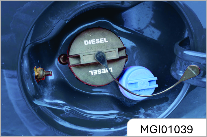
Consumption of the additive Diesel Exhaust Fluid (DEF) depends on the condition of vehicle use and is indicated by the Warning Light and / or the message on the instrument panel.
Diesel Exhaust Fluid (DEF) freezes at temperatures lower than 12°F (-11°C). If the car stands for a long time at this temperature refilling could be difficult. For this reason, it is advised to park the vehicle in a garage and / or heated environment and wait for the Diesel Exhaust Fluid (DEF) to return to liquid state before topping up.
Proceed as follows:
- Park the car on flat ground and stop the engine by placing the ignition in the OFF position.
- Open the fuel door, remove the Diesel Exhaust Fluid (DEF) filler cap.
Never fill Diesel Exhaust Fluid (DEF) or diesel fuel into the wrong filling ports. This may result serious damage to Engine, Fuel system and Emission system components. In case of wrongly filled do not start the engine, contact an JSW MG Authorized Service center.
At Each Stop for Fuel
Check the engine oil level about five minutes after a fully warmed engine is shut off. Checking the oil level while the vehicle is on level ground will impose the accuracy of the oil level reading.
- Check the windshield washer solvent and add if required.
- Check and top-up Diesel Exhaust Fluid (DEF) if required as indicated by the Warning Light and/or message on the instrument cluster.
It is recommended to visit the JSW MG Authorized Service center for refill / top up.
Refilling With Nozzles
Refilling With Nozzles
Proceed as follows:
- Insert the Diesel Exhaust Fluid (DEF) nozzle in the filler, start refilling and stop refilling at the first shut-off (the shut-off indicates that the Diesel Exhaust Fluid (DEF) tank is full). Do not proceed with the refilling, to prevent spillage of Diesel Exhaust Fluid (DEF).
- Extract the nozzle.
Refilling With Containers
Proceed as follows:
- Check the expiration date.
- Read the advice for use on the label before pouring the content of the bottle into the Diesel Exhaust Fluid (DEF) tank.
- If systems which cannot be screwed in (e.g. tanks) are used for refilling, after the indication appears on the instrument panel display refer to "Warning lights And Messages" in the "Getting To Know Your Instrument Panel" for further information, fill the Diesel Exhaust Fluid (DEF) tank with no more than 8 liters.
- If containers which can be screwed to the filler are used, the reservoir is full when the Diesel Exhaust Fluid (DEF) level in the container stops pouring out. Do not proceed further.
Operations After Refilling
Proceed as follows:
- Fit the cap back on the Diesel Exhaust Fluid (DEF) filler by turning it clockwise and screwing it completely.
- Place the ignition to ON POSITION (it is not necessary to start the engine).
- Wait for the indication on the instrument panel to switch off before moving the car. The indication may stay on for a few seconds to approximately half a minute. If the engine is started and the car is moved, the indication will remain on for longer. This will not compromise engine operation.
- If the Diesel Exhaust Fluid (DEF) was topped up when the tank was empty, wait for few minutes, until the warning light goes OFF and then start the engine.
- If Diesel Exhaust Fluid (DEF) is spilled out of the filler neck, clean up the area well and proceed to filling up again. If the liquid crystallizes, eliminate it with a sponge and warm water
- Do Not Exceed The Maximum Level: this could cause damage to the reservoir. Diesel Exhaust Fluid (DEF) freezes at under 12° F (-11° C). Although the system is designed to operate below the freezing point of the Diesel Exhaust Fluid (DEF), it is advisable not to fill the tank beyond the maximum level because if the Diesel Exhaust Fluid (DEF) freezes the system can be damaged. Follow the instructions in this section.
- If the Diesel Exhaust Fluid (DEF) is spilled on painted surfaces or aluminium, immediately clean the area with water and use absorbent material to collect the fluid that has been spilled on the ground.
- Do not try to start the engine if Diesel Exhaust Fluid (DEF) was accidentally added to the diesel fuel tank, this can result in serious engine damage, contactan authorized dealer.
- Do not add additives or other fluids to Diesel Exhaust Fluid (DEF), doing so could damage the system.
- The use of non-conforming or degraded Diesel Exhaust Fluid (DEF) may lead to indications appearing on the instrument panel display refer to "Warning Lights And Messages" in the "Getting To Know Your Instrument Panel" for further information.
- Never pour Diesel Exhaust Fluid (DEF) into another container; it could be contaminated.
- If the Diesel Exhaust Fluid (DEF) runs out, see refer to "Warning Lights And Messages" in the "Getting To Know Your Instrument Panel" for further information to continue using the car normally.
Once the engine is turned off, the Diesel Exhaust Fluid (DEF) pump rotates (a noise can be heard, which is normal) in reverse direction for approx 30 sec and in turn sucks the Diesel Exhaust Fluid (DEF) back into the tank. This prevents Diesel Exhaust Fluid (DEF) sedimentation in the Diesel Exhaust Fluid (DEF) hose and injectors.
4.3.7 Windshield Wiper
Foreign objects on the windshield and blade will reduce the effectiveness of the wiper. If the blade does not work properly, wipe the windshield and the blade with special or neutral washer solvent. Flush with water thoroughly. If necessary, repeat the above operation. Do not wipe the windshield with corrosive substances or materials that cannot be removed from the glass (e.g. silicone).
The strips have a layer of graphite on the surface for lubrication and protection. It should be protected from excessive wiping and undue polishing.
Do not start the wiper when the windshield surface is dry. Park the vehicle in a cool place as far as possible to prevent exposure to hightemperature, which will accelerate the aging and deformation of strips.
Remove foreign matters such as bird droppings, dust and leaves from the windshield surface before starting the wiper, otherwise, the service life of strips will be reduced.
strFront Wiper Blade Replacement:
The front wiper is of semi-concealed design. Before replacing the blade, operate the wiper to the maintenance position and then fold the wiper arm. Otherwise, the right wiper arm will contact the engine hood and damage the paint when being folded.
Method: Turn the ignition switch to ON position and then to LOCK position. Raise the wiper lever towards the steering wheel and release it (single-point contact) within 30s, and the wiper arm will swing to the maintenance position. After replacing the blade, lower the wiper arm and turn the ignition switch to ON position, and then the wiper will return to the original position.
Wiper Blade Removal and Installation
Fold the wiper arm on the windshield for operation.
As shown in the figure, firstly press the release switch of the wiper blade in the direction of arrow 1. Then hold the joint part between the wiper blade and the wiper arm with the other hand. Pull the wiper blade down slightly in the direction of arrow 2 to separate the wiper blade from the wiper arm.
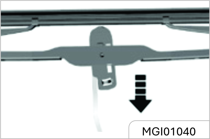
During installation, insert and clamp the new wiper blade into the U-slot of the wiper arm.
During the rear wiper blade removal, pull out the wiper blade from the installation point on wiper arm. For installation, align the blade with the installation point and press it into the point.
4.3.8 Air Filter
Check and replace the air filter element regularly according to the maintenance instructions in the Manual.
Air Filter Cleaning
If the air filter element is too dirty, clean it according to the following procedures:
- Shake the air filter element to remove floating dust.
- Clean the interior of air filter housing.
- Cover the filter housing with a wet cloth when cleaning the filter element.
- Clean the filter element with compressed air in the opposite direction of the engine intake.
Clean air is necessary for the normal operation of engine.
It is prohibited to drive the vehicle without the air filter element being installed. Otherwise, the engine will be damaged.
4.3.9 Drive Belt
For normal operation of engine and air compressor, the drive belt should be adjusted to a good state. In case of damage, break or wear, please replace the drive belt.
If the key is not pulled out, the engine may be start unintentionally during check. Do not leave the key in the ignition switch when checking the drive belt. Sudden running parts may cause serious personal injury when the engine is in operation.
4.3.10 Brake Pedal
Brake Pedal Travel Check
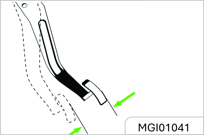
Brake pedal travel:
To avoid affecting the pedal travel, do not lay a thick carpet in the brake pedal area.
The reasonable range of brake pedal free travel is 0~30 mm.
If the brake pedal fails to return or the brake pedal travel becomes longer, please go to the JSW MG Authorized Service Center for inspection. This may indicate faults of the brake system.
4.3.11 Fuse
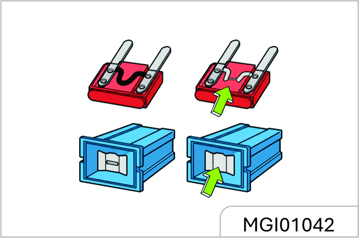
Fuse replacement:
- Open the fuse box cover.
- Identify damaged fuses by finding out blown fuses.
- Use a fuse extractor to remove the blown fuses. The fuse extractor is in the engine compartment fuse box.
- Figure out the cause of fusing and remove the fault.
- Install new fuses with rated current meeting the requirements.
Indoor Fuse Box
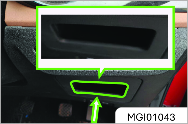
The indoor fuse box is on the lower right side of the instrument panel and it can be seen after pulling out the storage box.
Do not use a conductive tool to remove the blown fuse. The fuse extractor must be used. The use of metal and other electric conductors may cause a short circuit, damage the electrical system or cause a fire, resulting in serious personal injury.
Engine Compartment Fuse Box
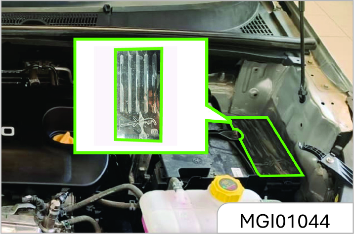
The engine compartment fuse box is next to the battery
The use of fuse substitutes or the fuse with an incorrect type and current rating may damage the electrical system or cause a fire. Be sure to use a fuse of the type and current rating that meets the requirements. Otherwise, it may cause personal injury and damage the vehicle and other properties.
Indoor Fuse Box Layout
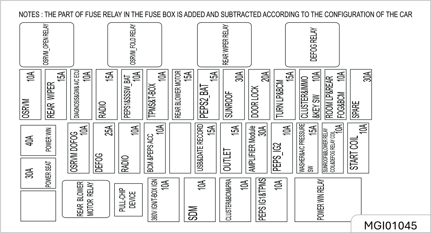
Engine Compartment Fuse Box Layout
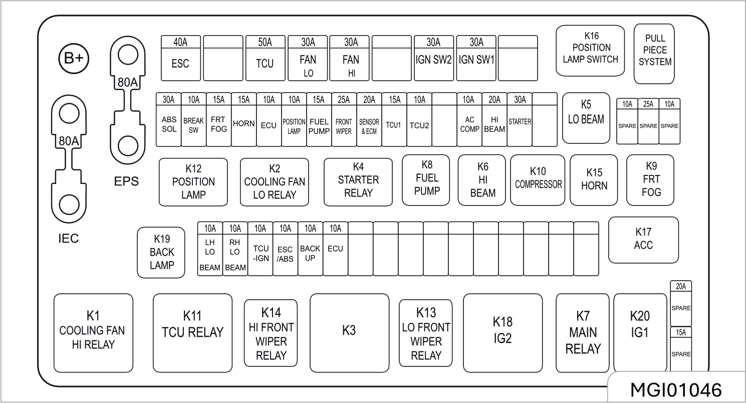
Lamp Bulb Replacement
The gas in the halogen bulb is under pressure. Handle with care and properly dispose of halogen bulbs.
- Wear safety glasses when removing or installing the lamp.
- Take care to prevent bulbs from wear and scratches.
- When the lamp lights up without being packaged, prevent the bulb from contacting liquids.
- Light up the lamp for test after the bulb being installed.
- Replace the cracked or damaged headlamp in time.
- Do not touch the glass portion with ungloved fingers when replacing the halogen bulb.
- Keep the bulb out of reach of children.
- Dispose of the old bulb carefully to prevent personal injury due to bulb explosion.
Clean the halogen bulb with alcohol or mineral spirits and non-woven fabrics. Do not touch the bulb with hands directly.
Fingerprints may significantly shorten the effective service life of halogen bulbs.
Professional skills and special equipment are required for replacement of bulbs. It is suggested to go to the JSW MG Authorised Service Center for help. Otherwise, it may cause personal injury or damage the vehicle.
Lamp Fogging
When the temperature is low or the air is humid, there may be water mist inside the lamp. Turn on the lamp, and the water mist will dissipate after a while. If it has resulted from the weather, repair is not necessary.
If the water mist does not dissipate after the lamp is turned on and there is more and more water vapor, please contact the JSW MG Authorized Service Center for inspection.
4.3.12 Wheels And Tyres
Original tyres guarantee optimum matching of riding comfort, tread life and performance.
Be sure to use wheels and tyres of specified specifications. The use of wheels and/or tyres of other specifications may result in abnormal operation of ABS and other relevant components and even cause collision accidents.
Please consult the JSW MG Authorised Service Center before replacing original tyres or wheels.
Otherwise, it may cause personal injury and damage the vehicle or other properties.
Maintenance
The tyre pressure shall meet provisions of the Manual so as to ensure optimum matching of driving comfort, safety and driveability.
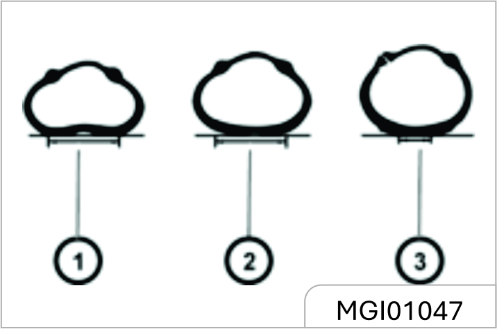
Refer to the tyre load information label for the correct tyre pressure. The label is on the sill plate below the driver’s door.
At the time of cold start, check the tyre pressure with an accurate tyre pressure gauge. After check of tyre pressure, tighten the valve core cap.
Make sure to check the tyre pressure at the time of cold start. The reading measured after the tyre temperature has increased shall not prevail. tyres will become hot after traveling for 1.6 Km and will not cool down completely within 3h after stopping.
Check the tyre pressure each time when refueling or at least every month. Incorrect tyre pressure may:
- Increase tyre wear
- Affect the vehicle manoeuvrability and safety
- Affect the riding comfort
- Reduce the fuel economy
How to check
Use a good quality tyre pressure gauge to check tyre pressure. You can not tell if your tyres are properly inflated simply by looking at them. Radial tyres may look properly inflated when they are underinflated. Remove the valve cap from the tyre valve stem. Press the tyre gauge firmly onto the valve to get a pressure measurement. If the
cold tyre inflation pressure matches the recommended pressure on the tyre and loading information label, no further adjustment is necessary. If the pressure is low, add air until you reach the recommended pressure. Make sure to put the valve caps back on the valve stems. Without the valve cap, dirt or moisture could get into the valve core and cause air leakage. If a valve cap is missing, install a new one as soon as possible.
If you overfill the tyre, release air by pushing on the metal stem in the centre of the tyre valve. Recheck the tyre pressure with the tyre gauge. Be sure to put the valve caps back on the valve stems. Without the valve cap, dirt or moisture could get into the valve core and cause air leakage. If a valve cap is missing, install a new one as soon as possible.
- Vehicle overload is prohibited.
- Be sure to keep a proper tyre inflation pressure.
- Be sure to check the tyre inflation pressure at the time of cold start (ambient temperature).
Excessively low tyre pressure will cause overheat of the tyre, leading to internal damage and layered tread and even tyre burst when driving at a high speed. Even if the tyre pressure was restored later, driving under too low pressure may have damaged the tyre.
Tyre and Wheel Maintenance
Running over sharp objects may damage tyres and wheels. If you have to run over these objects, please slow down.
Running over sharp objects may damage tyres and wheels. If you have to run over these objects, please slow down.
Regular Tyre Check
- Appearance damage.
- Foreign material.
- Piercing.
- Cut.
- Crack.
- Protruding on side wall.
It shall also inspect the wheel for damage.
Tyre defects including the above defects may lead to vehicle out of control, causing personal injury.
In case of damage or abnormal wear of tyre or wheel, please consult the JSW MG Authorized Service Center for help.
The vehicle is equipped with radial tyres. JSW MG Motor suggests replacing with radial tyres of the same size, pattern, tread wear, temperature and rated speed.
The use of tyres with different size than the original tyres may cause the tyre and the vehicle component to interfere with each other, thus causing damage to the tyre and vehicle.
If the vehicle is equipped with tyre pressure monitoring system, the tyre repairing liquid for tyre repair may result in the failure of the tyre pressure monitoring system sensor. It is suggested to go the JSW MG Authorised Service Center for inquiries and repair.
Internal Tread Wear Indicator
Check the tyre tread depth as per the tread wear indicator regularly. The mark on the tyre wall indicates the position of the tread wear indicator.
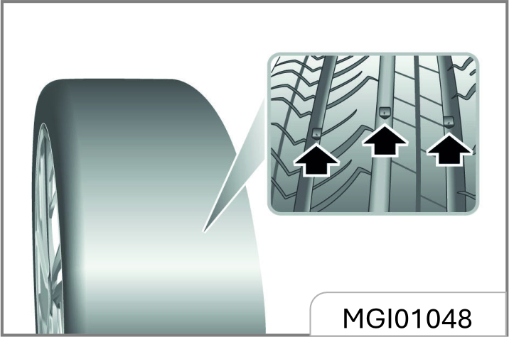
The tyre must be replaced when the tread wear indicator appears. When the tread depth is equal to or less than 1.6 mm due to wear, the tread wear indicator will appear between the tread grooves.
Do not drive the vehicle in case of tyre wear or damage. The worn or damaged tyres may lead to the vehicle out of control and cause collision accidents, resulting in personal injury and damage of vehicle or other properties.
Tyre Sidewall Labelling
This information identifies and describes the fundamental characteristics of the tire and also provides the tire identification number (TIN) for safety standard certification. The TIN can be used to identify the tire in case of a recall.
- Manufacturer or brand name Manufacturer or brand name is shown.
- Tire size designation
A tire’s sidewall is marked with a tire size designation. You will need this information when selecting replacement tires for your car. The following explains what the letters and numbers in the tire size designation mean.
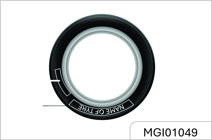
Example tyre size designation:
(These numbers are provided as an example only, your tire size designator could vary depending on your vehicle.)
215/60R17 96H
215 - Tire width in millimetres.
60 - Aspect ratio. The tire’s section height as a percentage of its width
R - Tire construction code (Radial). 17 - Rim diameter in inches.
96 - Load Index, a numerical code associated with the maximum load the tire can carry.
H - Speed Rating Symbol. See the speed rating chart in this section for additional information.
Wheel size designation
Wheels are also marked with important information that you need if you ever have to replace one. The following explains what the letters and numbers in the wheel size designation mean.
Example wheel size designation: 17 X 6.5J 17 - Rim diameter in inches.
6.5 - Rim width in inches.
J - Rim contour designation.
Tyre speed ratings
The chart below lists many of the different speed ratings currently being used for passenger vehicle tires. The speed rating is part of the tire size designation on the sidewall of the tire. This symbol corresponds to that tire’s designed maximum safe operating speed.
| Speed Rating Symbol | Maximum Speed |
|---|---|
| S | 180 km/h (112 mph) |
| T | 190 km/h (118 mph) |
| H | 210 km/h (130 mph) |
| V | 240 km/h (149 mph) |
| W | 270 km/h (168 mph) |
| Y | 300 km/h (186 mph) |
Wheel Alignment and tyre Balance
The wheels on your vehicle were aligned and balanced carefully at the factory to give you the longest tire life and best overall performance. In most cases, you will not need to have your wheels aligned again. However, if you notice unusual tire wear or your vehicle pulling one way or the other, the alignment may need to be reset. If you notice your vehicle vibrating when driving on a smooth road, your wheels may need to be rebalanced.
Improper wheel weights can damage your vehicle’s aluminium wheels. Use only approved wheel weights.
Tyre Rotation
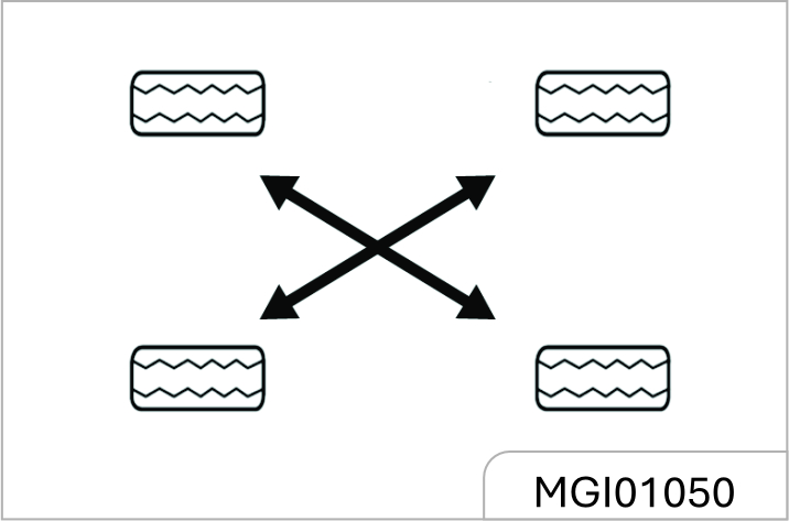
The front tyres and the rear tyres have different functions and therefore have different levels of wear. The front tyres wear faster than the rear tyres. In order to prolong the tyre life and avoid uneven tread wear:
- Conduct tyre rotation as per maintenance regulations in the Manual.
- Keep a proper tyre pressure.
- Check nuts/bolts for tightening.
When rotating tires, check for uneven wear and damage. Abnormal wear is usually caused by incorrect tire pressure, improper wheel alignment, out of-balance wheels, severe braking or severe cornering. Look for bumps or bulges in the tread or side of the tire. Replace the tire if you find any of these
conditions. Replace the tire if fabric or cord is visible. After rotation, be sure to bring the front and rear tire pressures to specification and check lug nut tightness.
Information
Tires that are asymmetrical or directional can only be installed on the wheel in one direction. The outside and inside of an asymmetrical tire is not easily distinguishable. Pay careful attention to the markings on the sidewalls of the tires, noting the "outside" marking and the rotating direction before installing them on the vehicle
Please use the recommended wheels and wheel nuts/bolts.
Otherwise, it may lead to the vehicle out of control and cause collision accidents, resulting in personal injury and damage of vehicle or other properties.
If the vehicle is equipped with tyre pressure monitoring system, after tyre rotation or tyre replacement, please go to the JSW MG Authorised Service Center to relearn the tyre pressure.
Winter Tyres
The use of winter tyres while driving on icy and snowy roads can improve driving safety. It is suggested to replace with winter tyres when the temperature is below 7 °C. Please select winter tyres with radial tyre structure and use such winter tyres on all four wheels. Please use the specified tyre pressure. Do not drive the vehicle at a speed exceeding the maximum speed specified by the tyre manufacturer. All- weather tyres can be used except winter tyres.
Tyre Chain
Tyre chains are only used for emergencies or in areas clearly defined by law and should be installed on the drive wheels. Be especially careful when driving the vehicle equipped with tyre chains. Compared with tyres without tyre chains, when tyres are installed with tyre chains, the maneuverability of the vehicle is poor, and the tyre chain may damage the vehicle tyre, suspension or vehicle body. Therefore, use cable tyre chains as far as possible to ensure enough space between the tyre and other parts in the wheel casing. When using tyre chains, carefully read the installation and other related instructions of the tyre chain manufacturer.
4.3.13 Spare Tyre*, Jack and Tools
Tool Kit
5-seat Model
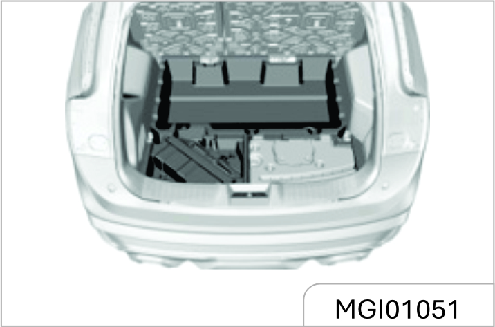
Spare Tyre*
The spare tyre, jack and tools are under the luggage compartment and can be seen after raising the luggage compartment floor. In- vehicle tools include the jack rocker, socket wrenches, traction hooks and screw drivers.
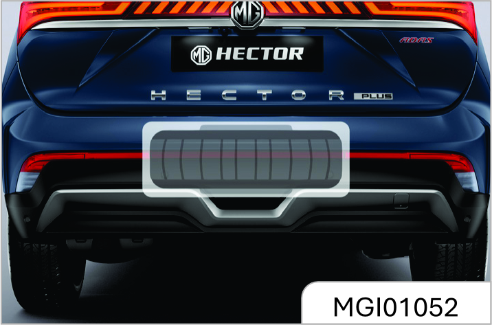
Take out the Spare Tyres
5-seat Model
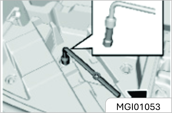
- Open the liftgate and raise the luggage compartment floor.
- Take out the tool bracket on the spare tyre. If the audio is equipped, disconnect its cable.
- Rotate the butterfly nut in the center of the spare tyre counter clockwise to remove it, and then place it properly
- Take out the spare tyre.
Jack Lifting Point
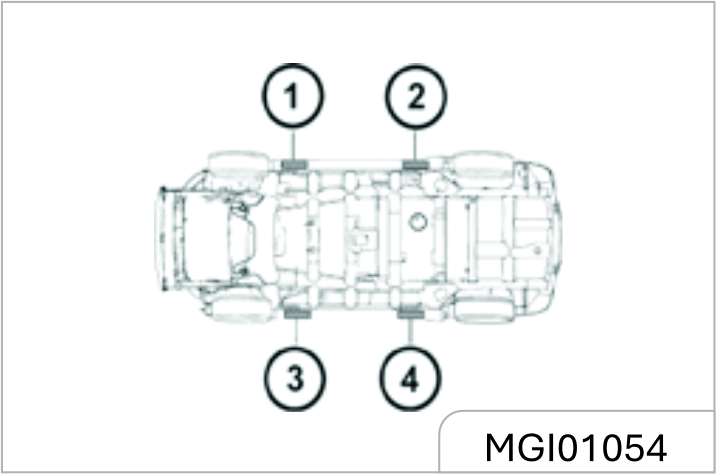
As shown in the figure above, the jack lifting points are around the side wall skirt, and there are triangle marks in corresponding parts for the convenience of searching.
These lifting points are also lifting points of the lifter, and the lifter tray should be aligned with the triangle mark. The lifting points have been specifically strengthened. Please be sure to align them.
Tyre Replacement
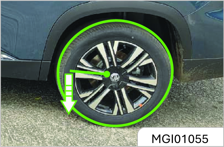
- Take out tools, the jack and spare tyre. Check and confirm that the tyre on the diagonal is secured with blocks or stones.
- Use a socket spanner to unscrew the wheel nut by one turn.
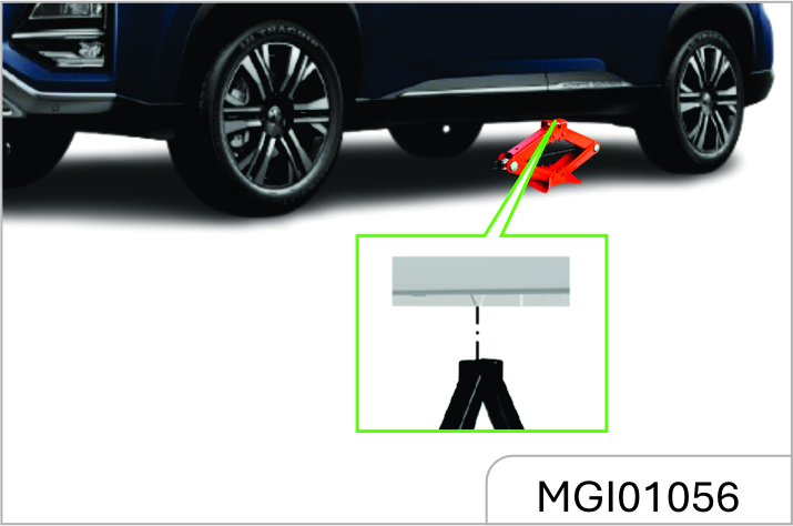
Place the jack just below the lifting point closest to the tyre that needs to be replaced. Align the slot on the jack head with the edge fold.
Do not remove any nut before wheels are lifted off the ground.
Do not attempt to lift the vehicle before the jack is put into a proper position. The jack should be firmly secured between the vehicle and the ground.
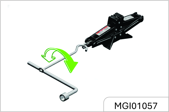
- As shown in the figure above, connect the jack rocker to the jack.
- Rotate the rocker clockwise to allow the jack to rise slowly and ensure that the jack head is firmly pushed into the lifting position.
- After ensuring that the jack is in the correct position, continue turning the rocker until the tyre is about 3cm off the ground.
- Place the spare tyre at the vehicle bottom near the wheel to be replaced so as to prevent the vehicle from suddenly slipping.
- Remove wheel nuts completely.
- Remove the wheel to be replaced.
- Install the spare tyre on wheel hub.
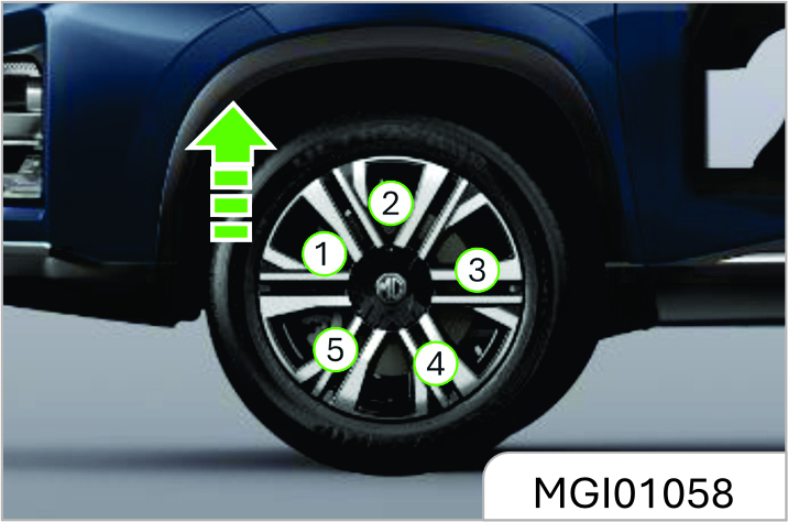
- Install all wheel nuts and tighten them preliminarily.
- Rotate the jack rocker counterclockwise to lower the vehicle to the ground stably.
- Tighten the wheel nuts in the order 1-4-2-5-3 as shown in the figure above with the torque of 100~130 N•m.
- Put the leaky tyre in the spare tyre storage location and secure it properly. Put tools back to the tool kit and secure them.
Make sure to use appropriate nuts and bolts, and tighten to the proper torque. The use of incorrect parts or improper tightening of vehicle nuts may cause damage to the vehicle or wheel falling off.
During the entire process the vehicle being lifted by the jack, ensure that the jack is placed vertically and no slipping occurs.
Do not lift the vehicle to a height that exceeds the necessary height for wheel replacement.
Please replace the deflated tyre as far as possible for further use. 1t shall check the spare tyres regularly to ensure that they can be used safely in case of emergency.
Do not work under the vehicle or start the engine when the vehicle is supported by a jack. The vehicle may slip off the jack, resulting in serious injury or death.
When the vehicle jacking condition is unsatisfactory or if you do not have the confidence to safely complete this work, please contact the JSW MG Authorised Service Center for help.
Do not apply oil or grease on the wheel nuts or bolts.
Please use correct wheel nuts or bolts. Use a socket wrench to tighten nuts or bolts firmly.
Please go to the JSW MG Authorised Service Center as soon as possible and tighten wheel nuts or bolts according to specification. In case of improper tightening, nuts or bolts may be loose, resulting in accidents.
When using the jack, the vehicle may become unstable and move, causing damage and personal injury. Please use the correct jack in normal state.
Before lifting, have all passengers leave the vehicle and stay away from traffic.
The jack is used for wheel replacement only.
Do not jack up the vehicle on a sloped or sliding ground.
Use the jack at the jack lifting point closest to the wheel that needs to be replaced.
Stop the wheel on the diagonal with wedges, blocks or stones so as to avoid vehicle moving.
Before using the jack, make sure that the parking brake is pulled up, the transmission is at Gear 1 or reverse gear and the DCT automatic transmission is at P gear.
Avoid replacing wheels at trafficintensive locations.
4.3.14 12V Battery
Warning notice on battery:
 Wear glasses!
 Wear protective gloves and
glasses since battery acid is highly
corrosive!
Wear protective gloves and
glasses since battery acid is highly
corrosive!
 Open flames, electric sparks,
strong light and smoking are
prohibited!
Open flames, electric sparks,
strong light and smoking are
prohibited!
 Explosive mixed gas may be
produced during battery charging!
Explosive mixed gas may be
produced during battery charging!
 Children should be kept away from
acid and battery!
Children should be kept away from
acid and battery!
Your vehicle is equipped with a MG authorized genuine battery, located in the front compartment.
Best Battery Service
- Keep the battery top clean and dry.
- Keep the terminals and connections clean, tight, and coated with petroleum jelly or terminal grease.
- Rinse any spilled electrolyte from the battery immediately with a solution of water and baking soda.
- Keep the battery securely mounted.
- Tighten loose terminals and hold down clamp nuts only enough to keep the battery firmly in place.
- Tightening excessively may damage the battery terminals.
To avoid battery discharge, please turn off the ignition switch when leaving the vehicle.
Do not leave the power tailgate open for a long period of time. This may drain the battery.
Unauthorized Electrical Devices
The vehicle can detect selfdischarge of the battery due to over-current that is generated by unauthorized electrical devices such as dashboard camera (dash cam) mounting during parking. If the warning continues even after external electrical devices are removed, have your vehicle inspected by a professional workshop.
Accessories-All accessories connected to the battery powered outlets should be removed or turned off when the vehicle is not in use to protect the battery against discharge.
It is advisable to avoid use of any 12V vehicle systems & accessories such as Power tail gate, Sound system, Interior & Exterior lamps, AC Blower, ….etc when engine is switched off. This may cause 12V battery to drain faster.
Risk of injury, corrosion, accident and fire exists when operating on vehicle battery and electrical appliance!
Wear protective glasses. Prevent acidic or lead particles from falling into eyes, on skin or clothes.
Wear protective gloves and glasses since battery acid is highly corrosive! The battery can not be turned over because the acid may flow out of the air vent. If the acid splashes into eyes, wash with clean water for a few minutes, then go to see a doctor immediately. If the acid splashes on skin or clothes, immediately neutralize it with rich soap solution and rinse with plenty of water. If you mistakenly drink acid, go to see a doctor immediately.
Open flames, electric sparks, strong light and smoking are prohibited! Avoid sparking when handling cables and electrical equipment a nd removing electrostatic loads. Battery electrode must not be shortcircuited because sparks with high energy pose a risk of injury.
A battery generates hydrogen gas which is flammable and explosive. Keep any flame or spark away from the vent holes.
Battery charging may produce explosive mixed gas, you must ensure that the battery air vent is open to successfully discharge the gas. The battery should be located in a well ventilated space during charging.
Children should be kept away from acid and battery.
Turn off the engine, ignition switch and all the electrical appliances before working on electrical appliances. Remove the battery negative cable. Turn off the lamp in bulb replacement.
Please pay attention to the polarity of power supply. check if the polarity of power supply matches before energizing.
Each energizing period should not be less than 5 seconds, to avoid frequent or fast on and off operation.
Turn off all the electrical appliances before energizing the battery again. First connect the positive cable, then the negative one. Do not connect the wrong cable - Risk of fire!
Unauthorized removal and installation of battery are prohibited, because in some cases, this operation will lead to serious damage to the battery and fuse box. Please contact Service Dealer.
Do not disconnect the battery when the ignition switch is on or the engine is running, otherwise it may damage the electrical appliances (electrical components).
To prevent the battery case from being exposed to ultraviolet light, do not expose the battery to sunlight.
Never attempt to dismantle a battery, they are sealed units.
While removing the battery, always disconnect the negative terminal first. And while installing the battery, ensure the negative terminal is connected last.
If the battery has been disconnected or a new battery has been installed, the preset radio (if equipped) stations will get reset, once the battery is reconnected.
The replacement battery must meet the specification of the MG recommended battery.
Car Parking Period
If the vehicle is to be parked for an extended period of time, the static current electrical appliance (like clock, security devices) will drain the battery, and the battery has to be recharged. To avoid such case, charge the battery or disconnect the battery negative cable during the vehicle parking.
Please pay attention to the warnings & instructions for battery before working on it.
Always turn off the ignition switch when parking, otherwise, it will greatly reduce the parking time.
Battery Charge With Ground Equipment
Don’t charge the frozen battery for the risk of explosion. Even if the battery has been unfrozen, battery acid may still overflow, resulting in corrosion damage. The frozen battery must be replaced.
Turn off the ignition switch and all electrical appliances before charging.
If the vehicle has been stored for an extended period of time, and can not be started due to battery undercharge (general terminal voltage 12V), the battery must be removed from the vehicle and charged with ground equipment (operating in accordance with the charging device manufacturer’s instructions).
When charging with a low current (such as a small charging device), generally it is not required to remove the battery connecting cables. But you must pay attention to the instructions given by the charging equipment manufacturer.
Before the quick charge, that is, before the high current charge, you must remove two connecting cables.
Please pay attention to the warnings & instructions for battery before working on it. When charging, the power supply of charging device can be switched on only after the charging device electrode chuck clipped to the battery electrode as specified. After charging, first turn o9 the charging device, unplug the power cord, and then remove the electrode chuck of charging device from the battery.
| Vehicle Type | Petrol | Diesel |
|---|---|---|
| Rating | 12V 75Ah | 12V 83Ah |
| Technology | Lead Acid | Lead Acid |
| CCA | 700A | 780 A |
| Dimension | 304(L) x 171(W) x 225(H) | 171(W) x 225(H) x 304(L) |
| Supplier | Exide | Exide |
Battery Spec/ratings may vary for Replacement case, please contact JSW MG authorized service centre.
- Keep children away from the battery, battery acid and charging devices.
- The battery can only be charged in an ventilated space. Smoking, open flame and electrical sparks are prohibited, because explosive mixed gas will be produced during battery charging!
- To protect your eyes and face, please stay away from the battery.
- If the acid splashes into eyes or on skins, rinse with clean water for a few minutes and go to see a doctor immediately.
- Battery fast charging is dangerous and should be performed by Service Dealer, because it requires specialized charging equipment and knowledge.
- Replace the frozen or unfrozen battery. Cracking may occur on the battery case because of freezing. Battery acid may leak and damage the vehicle.
Checking the Electrolyte Level
Check the electrolyte level and specific gravity at specific PMS intervals. Check proper electrolyte levels for all the cells. If the level is below the lower marker, add distilled water until the level reaches the upper marker.
Adding distilled water:
- Remove the vent plugs
- Add distilled water to all the cells that require the fluid and secure the plugs properly
Battery Removal
Turn off the ignition switch and all electrical appliance before removing the battery.
To remove the battery, you should first remove the negative cable, next the positive cable, and then remove bolts on the battery retaining bracket , finally remove the battery.
Battery Replacement
Please go to an MG Authorised Repairer to remove and refit the battery. Please note that the ignition switch and the electrical appliance have been turned off when installing the battery.
Only fit MG recommended battery while replacement to maintain the correct vehicle functionality.
Battery needs to dimensionally 0K, to avoid terminals fouling with Battery Tray.
 The used battery should not be
discarded at will, for it is harmful to the
environment. It must be recycled by
approved agencies. Please consult an
JSW MG Authorised Service Centre for
more details.
The used battery should not be
discarded at will, for it is harmful to the
environment. It must be recycled by
approved agencies. Please consult an
JSW MG Authorised Service Centre for
more details.
Battery Installation
Turn off the ignition switch and all electrical appliance before removing the battery. Place the battery in the mounting position and secure it with battery bracket. Secure the positive cable then the negative one, then energize the battery.
To avoid battery discharge, please turn off the ignition switch when leaving the vehicle.
The JSW MG Motor shall not be liable/ responsible for any damages/ injuries, including consequential damages / injuries, resulting due to fitment of non OEM approved batteries.
Jump Start (Dead Battery)
The vehicle with a low battery can be started by using the battery of other vehicles by the means of jump start.
If the battery is dead, please contact the JSW MG Authorized Service Center for handling unless you confirm that you have enough electrical knowledge and you can safely complete this work.
Do not start the vehicle by the means of pushing or dragging. Otherwise, it may damage the catalytic converter and the transmission and even personal injury.
Preparation before Jump Start
- Pull up the parking brake.
- Ensure that the gearshift lever is at the neutral or P position.
- Turn off all electrical accessories.
Turn off the audio system before jump start of the vehicle. Otherwise, the audio system will be damaged. Please turn off unnecessary electrical devices when the vehicle is running at low speed for long time (in case of traffic jam).
Jumper Cable Connection
In case of jump start of the vehicle, connect the jumper cable in the following order:
- Clip one end of the first jumper cable to the positive terminal of the powered battery.(There is a "+" mark on the battery housing or the terminal)
- Clip the other end of the jumper cable to the positive terminal of the dead battery.(There is a "+" mark on the terminal)
- Clip one end of the second jumper cable to the negative terminal of the powered battery. (There is a "-" mark on the battery housing or the terminal)
- Connect the other end of the cable to the body ground of the vehicle that has no electricity.
- While jump start, it is allowed to start the engine of the vehicle providing jump start power supply. Try to start the engine of the vehicle that has no electricity within one minute, and do not turn the ignition key more than 5s each time. After start, keep the rotation speed at 2000 (r/min) for several minutes.
- To remove the jumper cable carefully in reverse order, remove the negative cable first and then the positive cable.
There is the risk of battery explosion. You may be burned by the battery acid, and an electrical short circuit can also cause personal injury or damage to the vehicle.
- Do not place the battery near an open flame or sparks. Do not tilt the vehicle body over the battery in case of jump start.
- Do not allow cable terminals to contact with each other.
- Wear safety goggles when working nearby the battery.
- Do not allow battery acid to come into contact with eyes, skin, fabric or painted surfaces.
- Ensure that the battery used for jump start has the same voltage as the voltage of original vehicle battery.
- Do not disconnect a dead battery from the vehicle.
When starting the engine with jumper cables, violation of the above precautions or the following instructions can cause the battery to explode, resulting in people being burned by battery acid or causing a short circuit.
This may damage the electrical system of both vehicles and cause serious personal injury.
Position the jumper cable properly and do not wrap it around rotating parts of the engine compartment.
Otherwise, it may damage the vehicle and cause personal injury.
It shall not be connected to the negative (-) terminal of the battery when it is finally connected to the vehicle that needs to be charged.
Connect the last connected clip to the bolt on the engine cylinder block steel bracket. The last connection point should be away from the battery as far as possible.
If the jumper cable is connected to the negative terminal of an uncharged battery, it may produce electric arc and cause the battery to explode.
It will cause serious personal injury or damage the vehicle.
It shall start the engine of the vehicle with a discharged battery at an interval of about 1minute, and the time for each start cannot exceed 15s.
Do not use the battery as a jump source for other appliances for a long time. Otherwise, it is easy to make the battery lose electricity and may even cause safety accidents.
4.4 Vehicle Traction
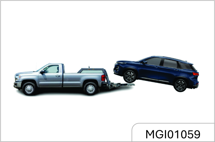
If vehicle traction is necessary, please contact the JSW MG Authorised Service Center or a professional traction service company
Do not tow the vehicle with lifting chain type equipment. It must use plates or wheel lifting equipment.
- It is prohibited to allow passengers to be seated in the towed vehicles.
- The towing speed is not allowed to exceed the safe speed or the indicated road speed limit.
- It is prohibited to use damaged parts that are not firmly secured onto the vehicle for traction. Failure to comply with the above precautions may result in personal injury.
Vehicle Traction with Wheel Lifter
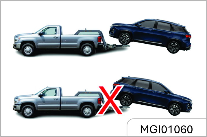
- Turn on the hazard warning flasher.
- Turn the ignition switch to ACC position.
- The transmission must be in neutral gear.
- Release the parking brake.
- Front wheels must be off the ground when towing.
Vehicle Traction with Platform Trailer
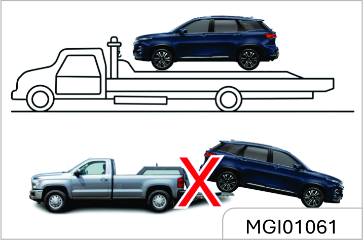
When towing the vehicle with a platform trailer, turn off the ignition switch and check that the vehicle is firmly attached to the trailer.
If the vehicle must be towed from the rear, please use traction device supporting wheels under the front wheels. The front wheels should not be on the ground when the vehicle is towed from the rear. Otherwise, it may cause serious damage to the vehicle transmission.
Emergency Trailer
If the trailer is not available in case of an emergency, it can secure the rope on the front towing hook under the vehicle for temporary vehicle traction. When the vehicle is towed via the front towing hook, only traction rope can be used. Do not use a rigid tow bar.
No matter MT or AT model, engage the neutral (N) gear and release the hand brake when the vehicle is towed.
On AT Model Traction
If the automatic transmission is faulty, the neutral (N) gear may not be engaged. In this case, if vehicle traction is required, the drive shafts of the two front wheels should be removed first; otherwise, the transmission may be damaged. It is suggested to contact the JSW MG Authorized Service Center for solution.
Front Towing Hook
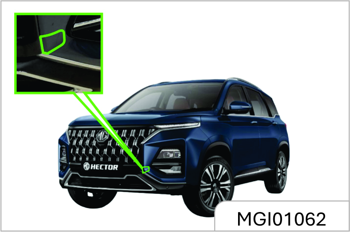
There is a hole cover on the right side of the front bumper of the vehicle. Open it and the fixing hole for hook installation can be seen.
The towing hook is on the tool bracket under the luggage compartment floor. Take out the towing hook and install it into the fixing hole. Rotate the towing hook clockwise to tighten it completely and insert a socket wrench into the hook hole to assist tightening. Be sure that the towing hook is installed firmly before towing the vehicle. When towing the vehicle, the driver must control steering and braking in the vehicle. After completion of traction, remove the towing hook and close the hole cover, and then put the towing hook back into the tool kit.
Rear Towing Hook
There is a hole cover on the left side of the rear bumper of the vehicle. Open it and the fixing hole for hook installation can be seen.
Take out the towing hook and install it into the fixing hole. Rotate the towing hook clockwise to tighten it completely and insert a socket wrench into the hook hole to assist tightening. Be sure that the towing hook is installed firmly before towing the vehicle.
Do not tow vehicles that are heavier than this vehicle; otherwise, it may damage the vehicle or cause accidents.
The vehicle may be damaged when it is towed by ropes. To reduce damage:
- The towing hook must be used when other traction devices are not available.
- The vehicle shall be towed from the front only.
- Keep the traction rope out of contact with the bumper.
- Make sure that both ends of the traction rope are firmly secured on the towing hook. Pull the traction rope for inspection.
- Drive the vehicle at a low speed and avoid sharp turning.
The vehicle may be out of control when it is towed by ropes.
To reduce damage:
- The towing distance shall not be too long, and the vehicle should be towed at a low speed.
- Do not tow the vehicle if the wheel, transmission, axle, steering or brake damage is damaged.
- Do not remove the key from the ignition switch; otherwise, the steering will be locked so that the vehicle cannot turn.
The towing speed shall not exceed 30 Km/h, and the towing distance shall not exceed 40 Km. When long-distance towing is required, it is suggested to contact the JSW MG Authorised Service Center or a professional towing service company for help.
4.5 Getting Vehicle out of Trap
When the vehicle is caught in snow, puddle or other unstable ground, please follow the procedures below to get the vehicle out of trap.
- Turn the steering wheel to the ultimate left and then turn it to the ultimate right. This will create a vacant area around the front wheels.
- Engage the reverse gear and drive gear back and forth.
- Reduce wheel idling as far as possible.
- Release the accelerator pedal when shifting gear.
- After engaging the gear, depress the accelerator pedal gently.
If it fails to get the vehicle out of trap, it is necessary to tow the vehicle.
When the vehicle is caught in snow, puddle or sandy soil, you need to get the vehicle out of the trap as soon as possible. First, check whether there are obstructions or people around the vehicle.
During operation, the vehicle may suddenly move forward or backward, hitting the person or object next to it.
In order to avoid damage to the transmission and other parts, the following precautions must be observed when getting the vehicle out of the trap.
- Do not depress the accelerator pedal during gear shifting or when the transmission is not in a proper gear position.
- High engine speed is not allowed, and wheel idling shall be avoided.
- If it fails to get the vehicle out of trap after several efforts, consider other methods, such as traction.
4.6 Vehicle Maintenance
Cleaning Agent
The manufacturer’s suggestions must be observed when using cleaning agent or other chemical products inside or outside the vehicle. Do not use dangerous cleaning agent when cleaning the interior and exterior of the vehicle. For example:
- Acetone
- Paint diluent
- Porcelain glaze reducing agent
- Nail polish remover
When cleaning the interior and exterior of the vehicle, the following cleaning agents are prohibited unless special instructions for cleaning stains are included in the fabric cleaning tips:
- Laundry soap
- Bleaching powder
- Reducing agent
Some cleaning agents are toxic , corrosive or flammable. Improper use is very dangerous and may easily cause personal injury or vehicle damage.
Do not use the following materials for cleaning:
- Carbon tetrachloride
- Gasoline
- Benzene
- Naphtha
When using any cleaning agent or other chemical products inside the vehicle, please open the doors for proper ventilation.
To avoid permanent color change of light- colored interior trims, do not allow the easy- to-discolor fabrics to come into contact with the seat liner unless both materials are completely dry. Fabrics with easy-to-discolor materials are:
- Casual clothes
- Dyed denim
- Leather
- Kidskin
Avoid prolonged exposure to cleaning agents and other chemical vapors. Such chemical vapor is extremely dangerous and harmful to the health, especially in limited space without ventilation.
Vehicle Interior Maintenance and Cleaning
Clean the interior and exterior of the vehicle with proper cleaning methods and materials.
Use a vacuum cleaner or a banister brush to remove dust and scum that accumulate on the fabric inside the vehicle frequently.
Wipe the vinyl plastics and leather trims regularly with a clean wet cloth.
Remove dust, spots or stains on trims with a suitable cleaning agent.
Clean the interior trims of the vehicle with proper cleaning methods and materials.
Otherwise, it will produce water spots, watermarks and permanent spots, especially during the first washing. These substances will permanently damage the vehicle.
Seat Belt Maintenance
Keep the seat belts clean and dry. Prevent seat belts from being contaminated by polishing agents, oils and chemical products, especially battery fluid, bleaching powder or dyestuff. These contaminants will reduce the strength of the seat belt material. Check all seat belt parts regularly. Replace any damaged seat belt or part immediately.
The seat belt or related parts that are stretched during the accident must be replaced, even if the damage is not obvious or is not visible. The seat belt for replacement must be new.
JSW MG Motor suggests replacing the whole seat belt assembly after collision. It is not necessary to replace the seat belt after it is checked to be undamaged and normal by the MG Authorised Service Center for solution.
The seat belt must be kept in good working condition to maintain its normal function.
Glass Surface
Make sure that the window glass is clean, which helps reduce glare and improve vision.
Front Windshield Outside Cleaning
Waxes or other materials on the front windshield and blade may cause the blade to shake when working. Moreover, such foreign matters are not conducive to keeping the front windshield clean. Clean the outside of the front windshield regularly with a non-abrasive cleaning agent.
Water does not form water droplets on the clean front windshield.
The non-abrasive cleaning agent will scratch the glass and damage the rear windshield defroster grid lines.
Do not use abrasive cleaning agent on vehicle glass. Otherwise, it will affect the driver’s vision.
Decals will affect the rear windshield defroster.
Do not paste decals on the inner side of the rear windshield. Otherwise, it will affect the driver’s vision.
Vehicle Exterior Maintenance and Cleaning
Vehicle Washing
The best way to maintain the finish paint of vehicles is to wash it regularly and keep it clean.
- Park the vehicle in the place where is not directly exposed to sunlight.
- Wash the vehicle with the specified neutral soap liquid and cold or warm water.
- Be sure to remove the soap liquid and cleaning agent from the surface by the means of flushing.
JSW MG Motor vehicles are designed to operate under normal environmental conditions and natural factors.
Do not use household dishwashing detergent to wash the vehicle. The dishwashing detergent can wash off paint and wax.
Avoid excessive vehicle washing pressure. Water may enter the vehicle and damage the interior.
Polishing and Waxing
Regular polishing can remove residues from the surface of the vehicle. After polishing, use high- quality car wax for protection.
It is forbidden to clean or polish aluminum trims with automotive or chrome polishing agent, steam or alkaline soap liquids. These substances are abrasive and may damage trims and wheels.
Exterior Bright Metal Parts Protection
Clean the bright metal trims regularly. They are usually washed with water. When waxing the vehicle, please also wax these bright metal parts.
Aluminium Wheels and Wheel Trim Cover Cleaning
To maintain the original appearance of the wheel and wheel trim cover (if any), do not allow them to collect dust or brake dust. Clean the wheel / wheel trim cover regularly. Do not use abrasive cleaning agent or brush that may damage the finish paint.
Do not use abrasive cleaning agent or brush to clean aluminum wheels or wheel trim covers.
- Keep yourself, test leads, clothing, and other objects clear of electrical connections and hot or moving engine parts.
- Do not wear watches, rings, or loose clothing when working in an engine compartment.
- Make sure no loose material (Cloth or other inflammable material etc) is left (but not limited to) inside engine compartment / Engine Cover / Fender after washing.
Corrosion Prevention
JSW MG Motor vehicles are designed to have anti-corrosion capabilities. The use of special materials and protective paint on most vehicle parts helps maintain satisfactory appearance, strength and reliability.
Although the surfaces of certain parts inside the engine compartment or of the underbody may rust, the reliability or performance of these parts will not be affected.
Metal Plate Damage
If the body needs to be repaired or replaced, ensure that the repair shop uses proper anti- corrosion materials to restore the anti- corrosion protection performance.
Foreign Matter Deposition
The following substances may damage the paint surface:
- Calcium chloride and other salts
- Ice melting agent
- Road surface oil and asphalt
- Sap
- Bird droppings
- Industrial dust
Remove harmful substances on the vehicle in time. If residues cannot be removed with soap liquid, a special cleaning agent can be used.
Finish Paint Damage
Repair the gravel scratches, cracks or deep scratches on the finish paint as soon as possible. Exposed metal is prone to corrosion. Quick- drying products can be used to repair tiny cracks and scratches. Body and paint repair shops can complete large-scale repairs.
Only safe cleaning agents that are harmless to the paint surface can be used.
Other cleaning agents may permanently damage the paint.
Underbody Maintenance
Corrosive substances used for ice and snow melting and dust prevention may accumulate at the underbody. Failure to remove these substances will accelerate corrosion and rusting.
Flush the underbody with clean water regularly. Clean the part where the mud is prone to accumulate carefully. Loosen the accumulated dirt in the enclosed area before flushing with water.
When necessary, please contact the JSW MG Authorized Service Centre for service.
4.7 Fuel
Fuel Recommendation
Fill Fuel as per the spec mentioned with respect to your vehicle & Compatibility. Using the fuel with an extremely low octane value will reduce power and torque of the engine, and increase the consumed fuel volume.
| Petrol* | Regular BSVI petrol min. RON91 (Recommended density of 720 - 775 kg/m3 at 15°C ) & Ethanol content ≤ E10 |
| Regular BSVI Petrol Min RON95 (Regular) RON98 (Premium) (Recommended Density of 720-775 Kg/m3 at 15°C) & Ethanol Content ≤ E20. | |
| Diesel* | Regular BSVI Diesel Min Cn51 (Recommended Density of 845 Kg/m3 at 15°C) & Sulphur Content ≤ 10ppm. |
Do not Use Methyl Alcohol
Do not use the fuel containing methyl alcohol on the vehicle. This fuel will reduce the vehicle performance and damage the fuel system components.
Driving in Other Countries
When driving your vehicle in other countries:
- Please follow all registration and insurance regulations.
- Confirm that the country can provide proper fuel.
- If you use any incorrect fuel, the engine and the catalytic converter will get seriously damaged.
- Always use the fuel suitable for your vehicle.
- For the purpose of safety, the fuel tank, pump and pipe must be grounded correctly.
- The static electricity will ignite vapor included in the gasoline. You will get burnt and the vehicle will get damaged.
- Never use alcohol or mix diesel with alcohol-based fuels including kerosene etc. It will damage the engine, fuel system and other related systems.
The fuel is one of flammables or explosives.
Smoking is prohibited. Keep away from open flames, sparks and smoking materials. If gasoline catches fire, serious burns will be caused and your vehicle will get damaged.
If you smell fuel Odors, please immediately ask JSW MG Authorised Service Centre to repair according to the fault cause.
- Using the fuel with an extremely low octane value will lead to uncontrolled burning and cause the engine to be damaged.
- Using the fuel containing methyl alcohol is not allowed for the vehicle design. Therefore, do not use the fuel containing methyl alcohol. As the methyl alcohol will corrode the metal parts in the fuel system and damage the plastic and rubber parts.
- The damage caused due to use of the fuel containing methyl alcohol is beyond the warranty scope. If contents of manganese and iron exceed the standard, the three-way catalytic converter may be blocked, and the spark plug misfires, etc. Therefore, please use the gasoline meeting requirements of the national standard.
- During cold weather conditions / freezing weather, diesel fuel thickens due to formation of paraffin layer. This results in difficulty of engine starting as there will be interruption of fuel supply to engine.
- It is advised to use locally available diesel fuel appropriate for the cold temperature conditions which are available at the filling stations during winter season.
- Please check with your fuel retailer for further details.
Shut down the engine and any heating devices provided outside the combustion chamber before refueling. Turn off all mobile phones.
Follow operation and safety instructions of gasoline station when refueling.
Fuel Filling
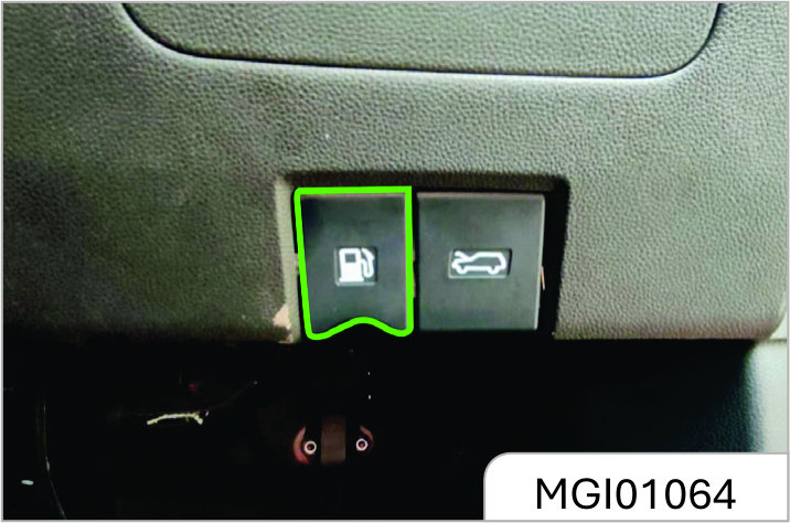
- Stop the engine from running.
- Pull up the filler flap release handle at the left lower side of the instrument panel to open the filler flap.
If you fail to open the filler flap in the cold weather, you can gently tap the filler flap. Then, try again.
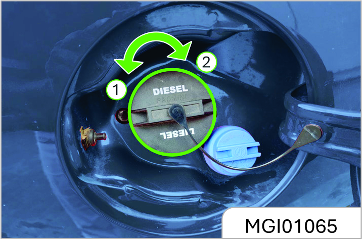
- Slowly turn the filler cap anticlockwise. If you hear the hissing sound, wait till the sound stops, and then unscrew the cap.
- Unscrew the filler cap. The filler cap is connected to the filler flap with a sling. Hang the sling to the hanger on the filler flap to secure the filler cap.
- Reinstall the filler cap after refuelling. Turn the filler cap clockwise till clicks are heard.
- Tightly close the filler flap.
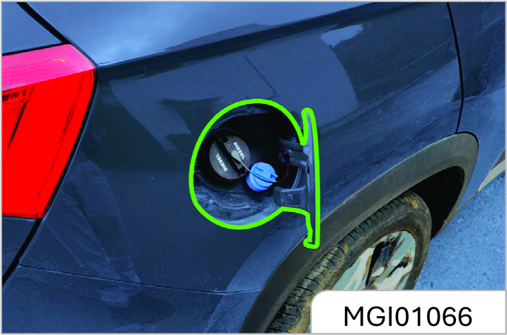
Mentioned if your vehicle is equipped with E20 fuel, E20 Sticker is pasted on the Fuel filler cap, fill the fuel as per spec mentioned.
"It is not recommended to fill fuel beyony auto cut off"
Never Use Leaded Fuel. This Could Deteriorate Catalytic Converter And Damage Emission Control System And Affect The Environment.
Technical Data
5.1 Vehicle Identification Information
Vehicle Identification Number (VIN)
There are 3 commonly used vehicle identification numbers on your car.
Vehicle Identification Markings
Seat floor vehicle identification number
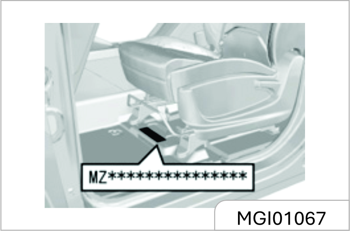
The VIN print stamp is located under the front passenger seat. Square floor.
Vehicle Identification Tag
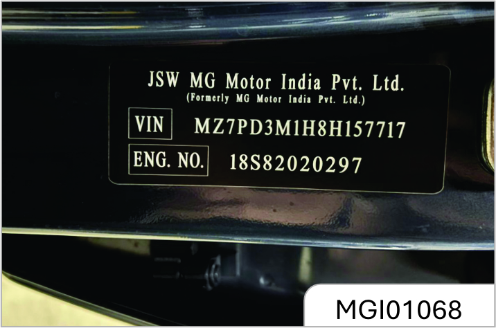
The sign is a paper sign and is located on the passenger side car. on the door frame.
Engine Identification Number
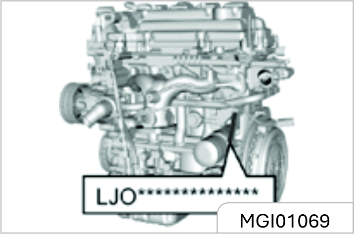
The rubbed stamp is located on the engine block. Near the flywheel.
5.2 Vehicle Data
Main Engine Performance Parameters
| Item | Unit | Parameter | |
|---|---|---|---|
| Engine Model: LJO | Engine Model: 46354460 / 46355956 / 46359207 | ||
| Engine Type | Four stroke Positive Ignition, IDI TCIC Four cylinder Inline Transverse mounted Turbocharged | Four Stroke, Water Cooled, In-Line, 16 Valve, DOHC,Timing Belt Drive, Direct Injection, Common Rail, VGT Turbo Charger with Electric Actuato | |
| Bore diameter × stroke | mm × mm | 73.8 × 84.7 | 83 × 90.4 |
| Displacement / Capacity | L | 1.451 | 1.956 |
| Compression ratio | - | 9.8 | 16.5 |
| Maximum net power / speed | kW / (r / min) | Net Power- 105k W @5000+/-200rpm | 125 / (3700 ~ 3800) |
| Maximum net torque | Nm / (r / min) | 250 / 1600-3600 | 350 / (1750 ~ 2500) |
| Idle Speed | r/min | 750±50 | 850±50 |
| Drive Type | Front wheel drive, forward | ||
| Complete vehicle emission standard | BS6 (OBD-II) | ||
Main Vehicle Quality Parameters
| Project | Unit | Parameter | ||||||||
|---|---|---|---|---|---|---|---|---|---|---|
| N15T 6MT | N15T CVT | 2.0D 6MT | ||||||||
| Number of People | 5 | 6 | 7 | 5 | 6 | 7 | 5 | 6 | 7 | |
| Curb Weight | kg | Style- 1545, Shine Pro/ Shine-1574, Select Pro/ Smart- 1592, Smart Pro1597, Sharp Pro-1636 | Sharp Pro1648 | Select Pro/ Smart1614, Sharp Pro1658 | Blackstorm-1673 100Y Edition-1673 Shine Pro/Shine-1610, Select Pro/ Smart-1628, Sharp Pro-1673, Savvy Pro- 1674 | Sharp Pro1685, Savvy Pro1686 | Blackstorm-1695 100Y Edition-1695 Sharp Pro1695, Savvy -1697 | Blackstorm-1751 100Y Edition-1751 Shine Pro/ Shine-1688, Select Pro/ Smart-1706, Smart Pro1711, Sharp Pro-1751, | Blackstorm1763 Smart Pro1723, Sharp Pro1763, Style-1681 | Blackstorm-1800 100Y Edition-1800 Select Pro/ Smart - 1728, Sharp Pro-1800 Style-1721 |
| Front axle load of curb weight | kg | Style-919, Shine Pro/ Shine-933, Select Pro/ Smart-939, Smart Pro942, Sharp Pro-955 | Sharp Pro962 | Select Pro/ Smart952, Sharp Pro-968 | Blackstorm-996 100Y Edition-996 Shine Pro/ Shine-969, Select Pro/ Smart-979, Sharp Pro-996, Savvy Pro- 997 | Sharp Pro995, Savvy Pro996 | Blackstorm-1001 100Y Edition-1001 Sharp Pro1001 Savvy Pro-1001 | Blackstorm-1047 100Y Edition-1047 Shine Pro/ Shine-1020, Select Pro/ Smart-1030, Smart Pro1033, Sharp Pro-1047 | Blackstorm1046 Smart Pro1032, Sharp Pro1046, Style-1012 | Blackstorm-1050 100Y Edition-1050 Select Pro/ Smart - 1043, Sharp Pro-1050 Style-1014 |
| Rear axle load of curb weight | kg | Style-626, Shine Pro/ Shine-641, Select Pro/ Smart-653, Smart Pro655, Sharp Pro-681 | Sharp Pro686 | Select Pro/ Smart662, Sharp Pro-690 | Blackstorm-677 100Y Edition-677 Shine Pro/ Shine-641, Select Pro/ Smart-649, Sharp Pro-677, Savvy Pro- 677 | Sharp Pro690, Savvy Pro690 | Blackstorm-694 100Y Edition-694 Sharp Pro694 Savvy Pro-695 | Blackstorm704 100Y Edition-704 Shine Pro/ Shine-668, Select Pro/ Smart-676, Smart Pro678, Sharp Pro-704, | Blackstorm-717 Smart Pro691, Sharp Pro-717, Style-669 | Blackstorm-750 100Y Edition-750 Select Pro/ Smart - 685, Sharp Pro750 Style-707 |
| Total mass | kg | 2100 | 2200 | 2200 | 2260 | 2260 | 2320 | |||
| Front axle load | kg | 1080 | 1105 | 1105 | 1145 | 1145 | 1200 | |||
| Rear axle load | kg | 1020 | 1095 | 1095 | 1115 | 1115 | 1120 | |||
| *Above values may vary depending on seating capacity of the vehicle. Please contact MG Dealer for more information | ||||||||||
Vehicle Main Size Parameters
| Project | Unit | Parameter Value | ||
|---|---|---|---|---|
| N15T 6MT | N15T DCT | 2.0D 6MT | ||
| Overall length | mm | Style- 4655mm / HECTOR PLUS Style DSL MT 6 str / 7 str - 4720 Shine / Smart / Smart Pro / Sharp Pro / Savvy Pro / Shine Pro/ Select Ro / Blackstorm 100Y Edition - 4699mm* | ||
| Total width | mm | 1835 | ||
| Total height (no load) | mm | 1760 | ||
| Wheelbase | mm | 2750 | ||
| Front overhang | mm | Style- 950/Style Dsl 6 str/7 str- 975 Shine/Smart/Smart Pro/Sharp Prp, SAVVY Pro/Shine Pro/Select Pro/ Black Edition/100Y Edition- 962 | ||
| Rear overhang | mm | Style- 950/Style Dsl 6 str/7 str- 995 Shine/Smart/Smart Pro/Sharp Prp, SAVVY Pro/Shine Pro/Select Pro/ Black Edition/100Y Edition- 987 | ||
| Front track | mm | 1554 | ||
| Rear track | mm | 1549 | ||
| Approach angle (no load/full load) | 20/19 | |||
| Departure angle (no load/full load) | 21/18 | |||
| Minimum ground clearance (full load) | mm | 174mm | CVT-185 mm | Diesel 149mm |
| Minimum turning diameter | mm | 11.9 | ||
Power / Dynamic Performance Parameter
| Project | Unit | Parameter | ||
|---|---|---|---|---|
| N15T 6MT | N15T CVT | 2.0D 6MT | ||
| Maximum Speed | Km/h | > 180km/h | > 180 | |
| Maximum climbin gradient | % | CVT- 11.31 degree MT- 12.95 degree Diesel- 12.95 degree | > 30 | |
| *Above values may vary depending on road condition and specific country regulation. Please contact MG Dealer for more information. | ||||
Main Liquid Parameter
| Name | Brand / Specification | Capacity, L | ||
|---|---|---|---|---|
| N15T 6MT | N15T CVT | 2.0D 6MT | ||
| Petrol* | Regular BSVI petrol min. RON91 (Recommended density of 720 - 775 kg/m3 at 15°C) & Ethanol content ≤ E10 | 60 | 60 | - |
| Petrol* | Regular BSVI Petrol Min RON95 (Regular) RON98 (Premium) (Recommended Density of 720-775 Kg/m3 at 15°C) & Ethanol Content ≤ E20. | 60 | 60 | - |
| Diesel* | Regular BSVI Diesel Min CN51 (Recommended Density of 845 Kg/m3 at 15°C) & Sulphur Content ≤ 10ppm. | - | 60 | |
| Engine Oil* | SP/GF-6 5W-30 | 4.0 | - | |
| SAE 5W30 ACEA C2 | - | 4.8 | ||
| Transmission Oil* | 75W/90 | 2.0±0.15 | - | - |
| FFFL-2 | - | 6.5±0.2 | - | |
| 75W | - | - | 2.0 | |
| Coolant* | Glycol type anti-freeze | 8±0.5L | 10±0.5L | |
| Brake fluid (including hydraulic Clutch solution)* | DOT4 | 0.75+0.05 | ||
| Air conditioning refrigerant* | HFC-134a | 690±20g (5 seats) 1050g±20g (7 seats) | ||
| Diesel Exhaust Fluid (DEF)* | Standard – ISO 22241 | As required | ||
| Engine Oil - 2.0 Liter Diesel Engine with Diesel Exhaust Fluid (DEF)* | SAE 0W-20 ACEA C2 | - | 4.8 | |
# Select the fuel to be added according to the label on the fuel filler port of vehicle’s tank.
For Diesel Variant:
It is recommended to use the regulated automotive diesel fuel confirming to IS 1460: 2017 spec only.
If the diesel fuel with high sulfur content (more than 10 PPM) and unspecified additives are used, it can cause damage to the DPF system and will not be covered under warranty.
For Petrol Variant (E10):
Use only commercially available Petrol fuel conforming to IS 2796: 2017 BSVI specification or equivalent (with Maximum 10% Ethanol content - E10 fuel) Information on Petrol quality can normally be found in the fuel pump. Please contact filling station personnel in case labels in the pump cannot be found.
For Petrol Variant (E20):
Use only commercially available Petrol fuel conforming to IS 17021 BSVI specification or equivalent (With Minimum of 20% Ethanol content – E20 fuel) Information on Petrol quality can normally be found in the fuel pump. Please contact filling station personnel in case labels in the pump cannot be found.
E20 Fuel is applicable for vehicle only with E20 Stickers on inside of Fuel filler cap.
Tyre Inflation Pressure (Cold State)
| Tyre Model | Wheel Size | Tyre Inflation Pressure (unit: Psi) |
|---|---|---|
| 215/60 R17 96H | 17*6.5J | 33 |
| 215/55 R18 95H | 18*7J | 35 |
Wheel Alignment Parameter (No-load)
| Project | Range (Unit: degree) | |
|---|---|---|
| Front Wheel | Camber | -26’±45’ |
| Caster | 40 15’±45’ | |
| Toe | 0±5’ | |
| King Pin Inclination | 1207’±10 | |
| Rear Wheel | Camber | -10±45’ |
| Toe | 11’±20’ | |
Other Parameters
| Project | Parameters |
|---|---|
| Requirement for dynamic balance of wheels | Dynamic unbalance < 15 g |
| Reasonable range of brake pedal free travel | < 30 mm |
| Minimum scrapping thickness of front brake disc | 25mm |
| Minimum scrapping thickness of front brake lining | 2mm |
| Minimum scrapping thickness of rear brake disc | 8mm |
| Minimum scrapping thickness of rear brake lining | 2mm |
5.3 Vehicle Tools
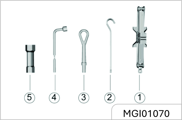
- Jack
- Jack Rocker
- Traction Hook
- Wheel Nut Wrench
- Sleeve
In case of any assistance please contact or reach nearest JSW MG Authorised service center. Scan the below QR code to navigate JSW MG dealer network:

www.mgmotor.co.in
1800 100 6464
JSW MG Motor India Pvt. Ltd.
All information, illustrations and specifications contained in this Owner’s Manual are based on the latest production information available at the time of publication. The right is reserved to make changes at any time without notice.
Version: 03-12/2025